
Metal button switch convenient to mount and dismount

A button and switch technology, applied in the electrical field, can solve the problems of reduced work efficiency, reduced safety performance, switch falling off, etc., to improve installation efficiency, avoid potential safety hazards, and achieve the effect of tightening effect

Inactive Publication Date: 2021-11-19
深圳宏源开泰科技发展有限公司
View PDF0 Cites 0 Cited by
  • Summary
  • Abstract
  • Description
  • Claims
  • Application Information

AI Technical Summary

Problems solved by technology

[0003] The existing metal button switches that are easy to install and disassemble have the following disadvantages: for example, they are basically fixed in the form of threads. Realize the fastening work automatically during the installation process, often after the installation is completed, it still needs to be fastened, resulting in a decrease in work efficiency, and finally there is no way to prevent the switch from falling off during use, which has potential safety hazards and reduces safety. performance

Method used


Image

  • Metal button switch convenient to mount and dismount
  • Metal button switch convenient to mount and dismount
  • Metal button switch convenient to mount and dismount

Examples


Embodiment 1

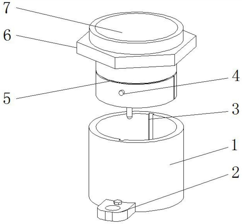
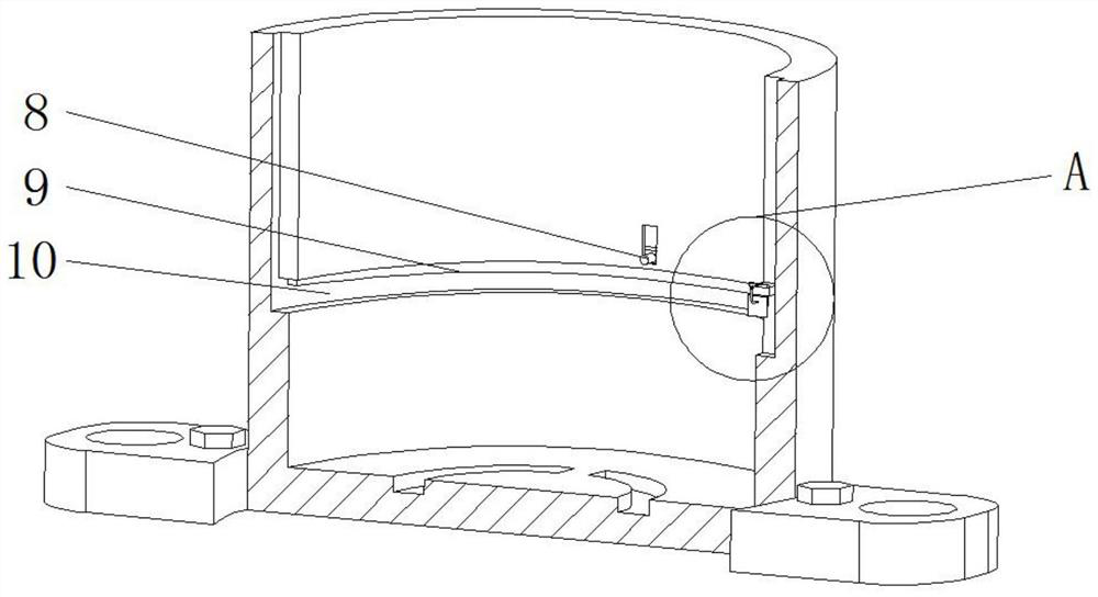
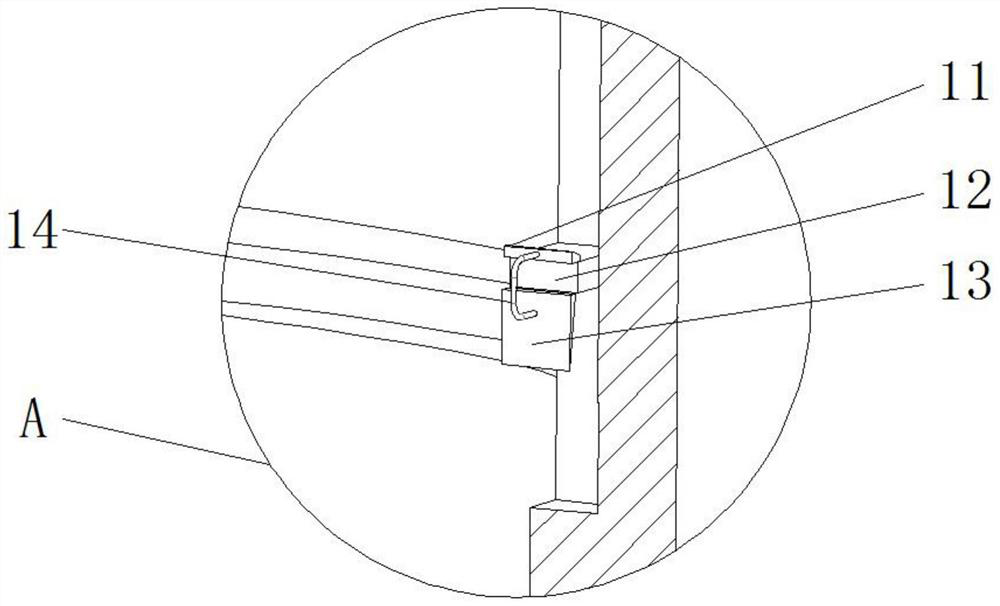
[0024] refer to Figure 1-4 , a metal button switch that is easy to install and disassemble, including a fixed tube 1, and two symmetrically arranged first chute 3s are opened on the arc-shaped inner wall of the fixed tube 1, and the arc-shaped inner wall of the fixed tube 1 is close to the two first chute 3 places Both are provided with fastening grooves 10, and the two fastening grooves 10 are respectively connected with the two first slide grooves 3, the top inner walls of the two fastening grooves 10 are provided with grooves, and the inner walls on one side of the two grooves slide A fastening plate 9 is connected, and the outer walls at the bottom of the two fastening plates 9 are slope structures. The outer walls on the opposite sides of the two fastening plates 9 are fixed with connecting rods 8 by bolts. The curved inner wall of the fixed pipe 1 is provided with two symmetrical settings. The through hole of the connecting rod 8 passes through, and the bottom of the in...

Embodiment 2

[0027] refer to Figure 1-3And 5, a metal button switch that is easy to install and disassemble, including a fixed tube 1, and the curved inner wall of the fixed tube 1 is provided with two symmetrically arranged first chute 3, and the curved inner wall of the fixed tube 1 is close to the two first chutes Fastening grooves 10 are provided at the three places, and the two fastening grooves 10 are respectively connected with the two first slide grooves 3, and the top inner walls of the two fastening grooves 10 are provided with grooves, and the inner walls on one side of the two grooves are Both fastening plates 9 are slidably connected, and the outer walls at the bottom of the two fastening plates 9 are slope structures. The outer walls on the opposite sides of the two fastening plates 9 are fixed with connecting rods 8 by bolts. Symmetrically arranged through holes are provided for connecting rods 8 to pass through. The bottom of the inner wall on one side of the two first chu...


PUM


Abstract

A metal button switch convenient to mount and dismount disclosed by the present invention comprises a fixed pipe, two symmetrically arranged first sliding grooves are formed in the arc-shaped inner wall of the fixed pipe, fastening grooves are formed in the arc-shaped inner wall of the fixed pipe close to the two first sliding grooves, and the two fastening grooves are communicated with the two first sliding grooves respectively. And grooves are formed in the inner walls of the tops of the two fastening grooves correspondingly, fastening plates are slidably connected to the inner walls of one sides of the two grooves correspondingly, the outer walls of the bottoms of the two fastening plates are of inclined plane structures correspondingly, and connecting rods are fixed to the outer walls of the opposite sides of the two fastening plates through bolts correspondingly. Through the arrangement of the first sliding grooves, the sliding blocks and the fastening grooves, in the installation process, only the two sliding blocks need to slide along the first sliding grooves, when the sliding blocks slide to the fastening grooves, installation can be completed by rotating the shell and rotating the sliding blocks into the fastening grooves, and the situation that the service life is shortened due to threaded installation is avoided.

Description

technical field [0001] The invention relates to the field of electrical technology, in particular to a metal button switch which is easy to install and disassemble. Background technique [0002] The push button switch refers to the switch that uses the button to push the moving contact and the static contact to connect or disconnect and realize the circuit switching. When the push button switch is needed, it is inevitable to install the push button switch, which requires a Metal button switch for easy installation and removal to facilitate the process of installation and removal. [0003] The existing metal button switches that are easy to install and disassemble have the following disadvantages: for example, they are basically fixed in the form of threads. Realize the fastening work automatically during the installation process, often after the installation is completed, it still needs to be fastened, resulting in a decrease in work efficiency, and finally there is no way ...

Claims


Application Information

Patent Timeline
Patent Type & Authority Applications(China)
IPC IPC(8): H01H13/10H01H13/02
Inventor 徐征
Owner 深圳宏源开泰科技发展有限公司
Learn More