
Double-head mechanical stirring type flotation machine

A mechanical stirring and flotation machine technology, used in flotation, solid separation and other directions, can solve the problems of insufficient ore particles, long time required for flotation separation, insufficient suction capacity, etc. The range of stirring, the effect of high work efficiency

Inactive Publication Date: 2021-11-16
郭彦斌
View PDF0 Cites 0 Cited by
  • Summary
  • Abstract
  • Description
  • Claims
  • Application Information

AI Technical Summary

Problems solved by technology

[0003] When the flotation machine is working, the motor drive is used to drive the impeller to rotate to achieve the function of stirring. When the impeller rotates, negative pressure will be generated to suck the air and mix it with the ore pulp, so that the ore particles are fixed on the air bubbles and floated up and scraped off. The existing machinery The agitated flotation machine is fixed as a whole and adopts the impeller installed vertically downward, so that not only the range is small when rotating, but also the area where the air is stirred and mixed is limited to some places, which leads to uniformity. The performance is very poor, the separation effect is not very ideal for long-term work, and the time required for sufficient flotation separation is longer;
[0004] The mechanical agitation flotation machine uses the negative pressure suction when the impeller rotates. Although this method saves the aeration structure, the aeration volume is small, and it is not suitable for all types of pulp separation flotation. When the speed is fast, the impeller produces Negative pressure is enough to inhale sufficient air, but when the speed slows down, it will cause insufficient air inhalation, which will result in less air bubbles in the stirred pulp, so that the ore particles cannot be fully floated out, resulting in insufficient separation. It is sufficient, and it is necessary to perform flotation again to waste time. At the same time, the suitable air intake volume cannot be adjusted according to the rotational speed during flotation. If the negative pressure adjustment of the impeller itself is used, it will only cause insufficient air, and adding an additional inflatable structure will It increases the cost and requires manual adjustment, and the work efficiency is still not high

Method used


Image

  • Double-head mechanical stirring type flotation machine
  • Double-head mechanical stirring type flotation machine
  • Double-head mechanical stirring type flotation machine

Examples


Embodiment Construction

[0022] The following will clearly and completely describe the technical solutions in the embodiments of the present invention with reference to the accompanying drawings in the embodiments of the present invention. Obviously, the described embodiments are only some, not all, embodiments of the present invention. Based on the embodiments of the present invention, all other embodiments obtained by persons of ordinary skill in the art without making creative efforts belong to the protection scope of the present invention.

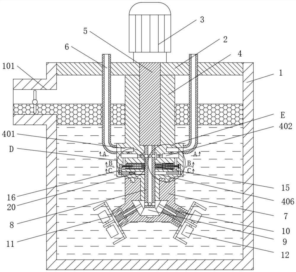
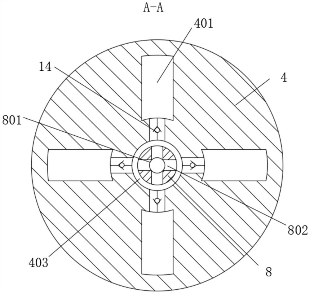
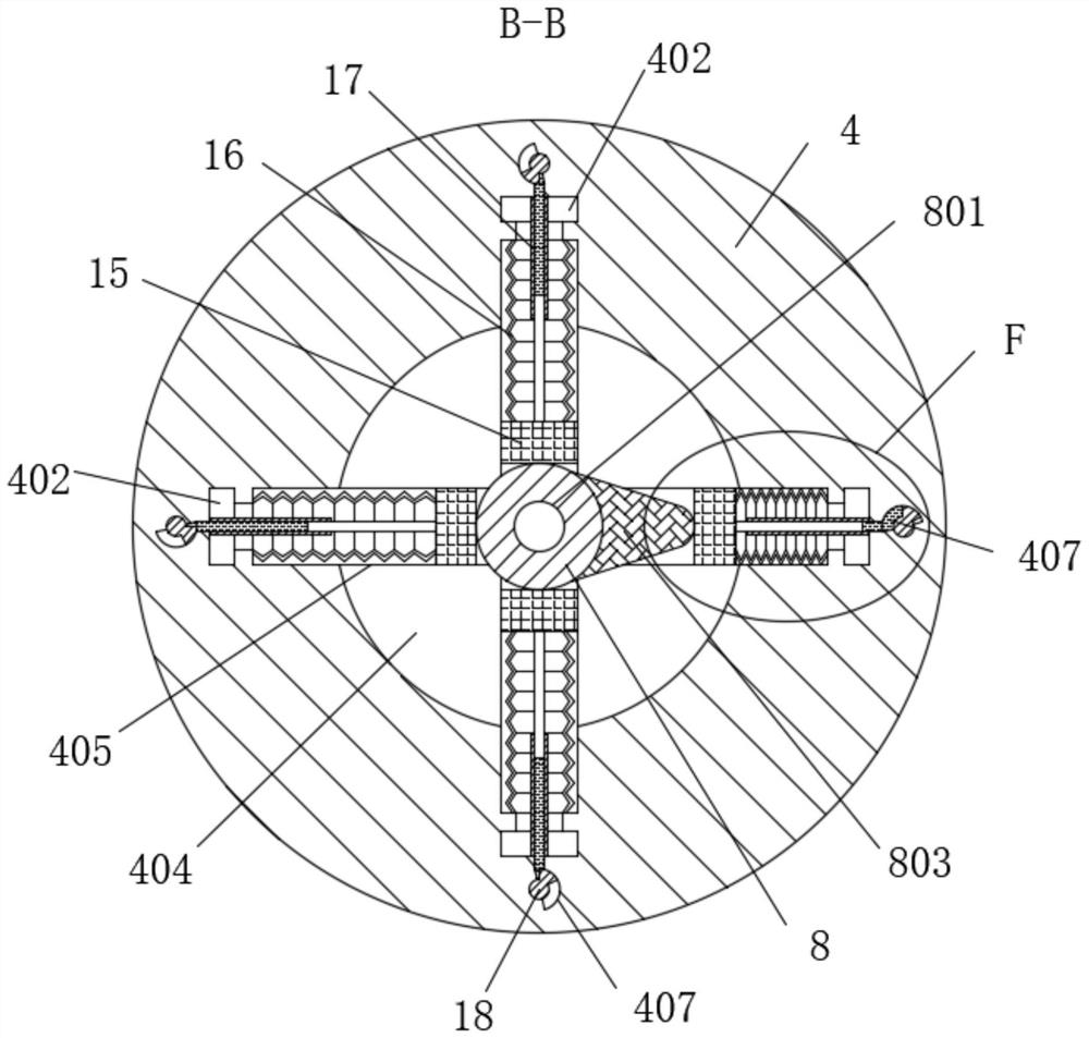
[0023] Please refer to the attached Figure 1-4 , a double-head mechanical stirring type flotation machine, comprising a tank body 1, a scraper opening 101 is provided at the top position of one side of the tank body 1, a top cover 2 is fixedly installed on the top of the tank body 1, and the middle of the top cover 2 top is fixed A motor 3 is installed, a center cylinder 4 is fixedly installed in the middle of the bottom of the top cover 2, and a drive shaft ...


PUM


Abstract

The invention relates to the technical field of beneficiation mechanical equipment, and discloses a double-head mechanical stirring type flotation machine which is characterized in that air cavities communicating with a central cylinder are annularly and uniformly formed in the position, located at the bottom of an air inlet ring groove, in the central cylinder, and a sleeve movably sleeves the outer ring of the bottom of the central cylinder; transmission shafts in meshing transmission with the bevel gears are symmetrically and movably installed in the two sides of the bottom of the sleeve; a protruding block is fixedly installed at the position, located in the first rotating cavity, of the outer ring of the main shaft; a corrugated pipe is fixedly connected between the sliding block and the sliding groove; a telescopic rod is movably connected between the middle of the side, close to the corrugated pipe, of the sliding block and the inner wall of the air cavity; a rotating head with the bottom fixedly connected with the rotating shaft is movably sleeved with the hydraulic cavity; and a centrifugal block is movably sleeved with the end of the rotating sleeve. The structure that two ends rotate and the whole sleeve can rotate is adopted, and movable adjusting structures such as the corrugated pipe, the telescopic rod and the rotating head are arranged in the center cylinder, so that the separation effect and the separation efficiency of the flotation machine are improved.

Description

technical field [0001] The invention relates to the technical field of mineral processing machinery and equipment, in particular to a double-head mechanically agitated flotation machine. Background technique [0002] The flotation machine, also known as the flotation concentrator, performs flotation on the pulp treated with chemicals, and through agitation and aeration, some of the ore particles are selectively fixed on the air bubbles and float to the surface of the pulp to be scraped off to form foam. Keep the remaining part in the pulp to achieve the purpose of separation. The mechanical stirring flotation machine is a commonly used flotation machine. It has the advantages of self-suction air, less auxiliary equipment, and simple operation and maintenance, but it still has certain shortcomings. at: [0003] When the flotation machine is working, the motor drive is used to drive the impeller to rotate to achieve the function of stirring. When the impeller rotates, negativ...

Claims


Application Information

Patent Timeline
IPC IPC(8): B03D1/16
Inventor 郭彦斌
Owner 郭彦斌
Learn More