Motion control method and device based on electronic cam curve

An electronic cam and motion control technology, applied in the direction of electrical program control, sequence/logic controller program control, etc., can solve the problems that cannot meet the needs of various motion control scenarios, and the electronic cam curve has few styles, etc., to achieve richness The effect of the e-cam curve pattern

Active Publication Date: 2021-11-09
SHENZHEN INVT ELECTRIC
View PDF14 Cites 2 Cited by
  • Summary
  • Abstract
  • Description
  • Claims
  • Application Information

AI Technical Summary

Problems solved by technology

[0007]However, the current electronic cam curves have fewer styles and cannot meet the needs of various motion control scenarios

Method used


Image

  • Motion control method and device based on electronic cam curve
  • Motion control method and device based on electronic cam curve
  • Motion control method and device based on electronic cam curve

Examples


Embodiment Construction

[0043]Exemplary embodiments of the present invention will be described in more detail below with reference to the accompanying drawings. Although exemplary embodiments of the present invention are shown in the drawings, it should be understood that the invention may be embodied in various forms and should not be limited to the embodiments set forth herein. Rather, these embodiments are provided for more thorough understanding of the present invention and to fully convey the scope of the present invention to those skilled in the art.

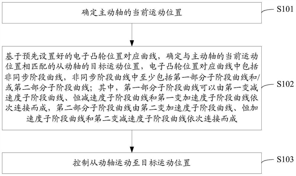
[0044] Such as figure 1 As shown, this embodiment proposes the first motion control method based on the electronic cam curve. The method may include the steps of:

[0045] S101. Determine the current movement position of the driving shaft;

[0046] Wherein, the active shaft may be a feed shaft whose motion is controlled by an encoder, or a feed shaft whose motion is controlled by other means, such as a servo shaft controlled by an Ethercat bus...


PUM


Abstract

The invention discloses a motion control method and device based on an electronic cam curve, which can determine the motion position of a driving shaft and determine the target motion position of a corresponding driven shaft based on an electronic cam position corresponding curve, and the electronic cam position corresponding curve comprises an asynchronous stage curve. The asynchronous stage curve at least comprises a first part of sub-stage curve and/or a second part of sub-stage curve, and the first part of sub-stage curve can be formed by sequentially connecting a first variable deceleration sub-stage curve, a constant deceleration sub-stage curve and a first variable acceleration sub-stage curve; the second part sub-stage curve is formed by sequentially connecting a second variable acceleration sub-stage curve, a constant acceleration sub-stage curve and a second variable deceleration sub-stage curve, and the driven shaft is controlled to move to the target movement position. The electronic cam position corresponding curve provided by the invention can effectively enrich electronic cam curve styles, so that motion control functions required by more motion control scenes can be effectively realized.

Description

technical field [0001] The invention relates to the technical field of motion control, in particular to a motion control method and device based on an electronic cam curve. Background technique [0002] With the development of science and technology, motion control technology continues to improve. [0003] A mechanical cam is a physical mechanism that enables the driving shaft and the driven shaft to meet a specific positional relationship during motion. It can be widely used in motion control fields such as chasing shears, flying shears, and labeling. Due to the difficulty in design and manufacture of mechanical cams, the difficulty of manufacturing precision to meet the requirements of motion control, and the ease of wear during motion, mechanical cams are gradually replaced by electronic cams. [0004] The electronic cam is a control system that can achieve a specific positional relationship between the driving shaft and the driven shaft by generating an electronic cam c...

Claims


Application Information

Patent Timeline
Patent Type & Authority Applications(China)
IPC IPC(8): G05B19/06
CPCG05B19/06
Inventor 黄海飞尚波杜肖丰杨志朋
Owner SHENZHEN INVT ELECTRIC
Why Eureka
Try Eureka