Automatic dredging device for chlorine spray gun of molten salt chlorination furnace

A molten salt chlorination furnace and chlorine technology, which are applied in injection devices, titanium tetrachloride, titanium halide and other directions, can solve the problems of low efficiency, time-consuming and laborious chlorine spray gun dredging, etc., and achieve high efficiency, eliminate potential safety hazards, hammer blow powerful effect

Active Publication Date: 2021-11-09
云南国钛金属股份有限公司
View PDF7 Cites 0 Cited by
  • Summary
  • Abstract
  • Description
  • Claims
  • Application Information

AI Technical Summary

Problems solved by technology

[0005] Aiming at the time-consuming, labor-intensive, low-efficiency and potential safety hazards of chlorine spray gun dredging in the prior art, the present invention provides an automatic dredging device for chlorine spray gun of molten salt chlorination furnace , the purpose of which is to: improve the efficiency of dredging the chlorine spray gun and eliminate potential safety hazards

Method used


Image

  • Automatic dredging device for chlorine spray gun of molten salt chlorination furnace
  • Automatic dredging device for chlorine spray gun of molten salt chlorination furnace
  • Automatic dredging device for chlorine spray gun of molten salt chlorination furnace

Examples


Embodiment 1

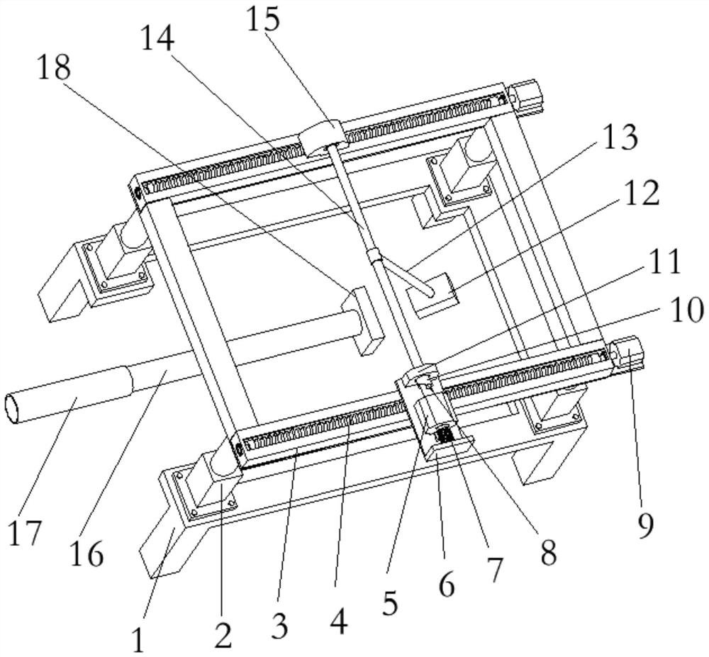
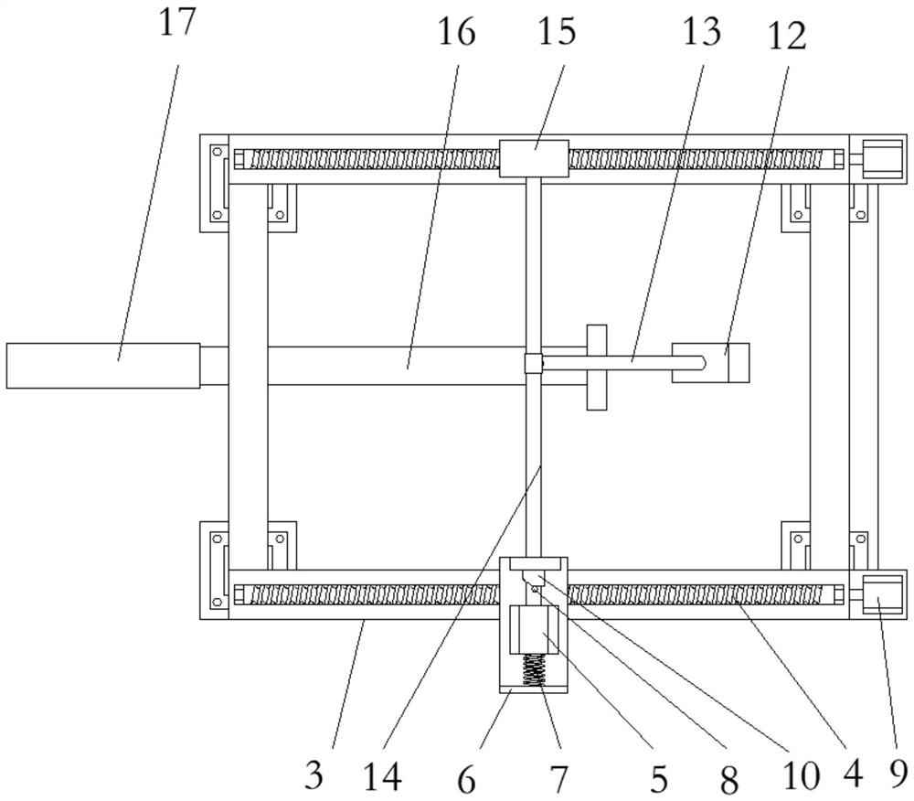
[0047] A kind of molten salt chlorination furnace chlorine spray gun automatic dredging device, such as figure 1 As shown, it includes a base 1 and a chlorine spray gun needle 16. The base 1 is provided with a lifting platform, and the lifting platform includes four hydraulic cylinders 2 and a moving frame 3 at the top of the hydraulic cylinders 2. The bottom of the lifting mechanism It is fixedly connected with the base 1, and the top is fixedly connected with the motion frame 3. Both sides of the moving frame 3 are provided with a longitudinal movement mechanism, and the longitudinal movement mechanism includes two linear modules respectively arranged on both sides of the moving frame 3 , and the linear modules include a servo motor 9 and a lead screw 4 . Both the second drive shaft mount 15 and the motor base 6 are connected to the lead screw 4 . The servo motor 9 drives the screw 4 to rotate, which can make the second transmission shaft mounting base 15 and the motor base...

Embodiment 2

[0057] The technical solution of this embodiment is basically the same as that of Embodiment 1, the difference is that in this embodiment, the motor 5 is fixed on the motor mount 6, the output shaft of the motor 5 is connected with a half gear 20, and the transmission shaft 14 is connected with full gear 21, and said full gear 21 cooperates with half gear 20.

[0058] When the motor output shaft 22 rotates, when the half gear 20 meshes with the full gear 21, the motor 5 drives the transmission shaft 14 to rotate, thereby driving the weight 12 to move upward. When the half gear 20 rotates to disengage from the full gear 21, the weight The hammer 12 has been raised to the highest point and moves downward from the highest point to hammer the needle cap 18 . When the half gear 20 is meshed with the full gear 21 again, the weight 12 is promoted again, and so reciprocated, the dredging of the chlorine gas spray gun is realized.


PUM


Abstract

The invention discloses an automatic dredging device for a chlorine spray gun of a molten salt chlorination furnace, and belongs to the technical field of chemical production. The problems that in the prior art, chlorine spray gun dredging wastes time and labor, is low in efficiency and has potential safety hazards are solved. The device comprises a base (1) and a chlorine spray gun poking needle (16), wherein a lifting platform is arranged on the base (1), a transmission mechanism and a driving mechanism are arranged on the lifting platform, the transmission mechanism is connected with a heavy hammer mechanism, and the driving mechanism drives the heavy hammer mechanism to do reciprocating motion through the transmission mechanism to hammer the chlorine spray gun poking needle (16). Manpower is replaced by mechanical force, so that the poking needle is efficiently driven in and taken out, the furnace outage time of the chlorination furnace is shortened, the production efficiency is improved, and meanwhile, the potential safety hazard of chlorine emission when the poking needle is driven manually is eliminated.

Description

technical field [0001] The invention belongs to the technical field of chemical production, and in particular relates to an automatic dredging device for a chlorine spray gun of a molten salt chlorination furnace. Background technique [0002] In the process of producing titanium tetrachloride by the molten salt chlorination process, the chlorine gas spray gun is the only channel for chlorine gas to enter the furnace. During the production process of the chlorination furnace, the chlorine gas spray gun must be kept unobstructed so that the molten salt in the furnace can circulate continuously. In this way, the chlorine gas can fully react with the powdered raw materials added to the furnace. Therefore, the chlorine spray gun is equivalent to the respiratory organ of the chlorination furnace, and the opening and closing of the chlorine spray gun plays a vital role in the operation of the chlorination furnace. [0003] At the same time, as the production progresses, the molte...

Claims


Application Information

Patent Timeline
IPC IPC(8): B05B15/522C01G23/02
CPCB05B15/5223B05B15/522C01G23/022
Inventor 张美杰刘峰和奔流陈建立李建军祝永红王丽艳张军丽杨倩张建林张燕平赵冠杰杨德
Owner 云南国钛金属股份有限公司
Why Eureka
Try Eureka