Valve clamping system

A technology of valves and clips, applied in the direction of heart valves, valve rings, etc., can solve problems such as complex adjacent structures, damage to surrounding tissues, thin valve leaflets and tendon chords, etc., to reduce the risk of surgery, reduce the difficulty of clamping, and operate Simple and convenient effect

Pending Publication Date: 2021-11-09
SHANGHAI SHENQI MEDICAL TECH CO LTD
View PDF6 Cites 1 Cited by
  • Summary
  • Abstract
  • Description
  • Claims
  • Application Information

AI Technical Summary

Problems solved by technology

Compared with the mitral valve, the tricuspid valve has a larger valve ring and valve area, with the greatest variability, the valve ring tissue is more fragile, and the valve leaflets and chordae are thinner; the adjacent structure is complex, and it is easy to cause damage to the surrounding tissue; the valve ring It is half-moon saddle-shaped, irregular in shape and most likely to expand, and the degree of tricuspid regurgitation is most likely to be affected by volume load; in addition, there are abundant muscle trabeculae, meat columns and chordae in the right ventricle, and the free wall is weak; and the right ventricle Low blood flow rate is easy to form thrombus, which poses a great challenge to the design and application of surgical instruments

Method used


Image

  • Valve clamping system
  • Valve clamping system
  • Valve clamping system

Examples


Embodiment 1

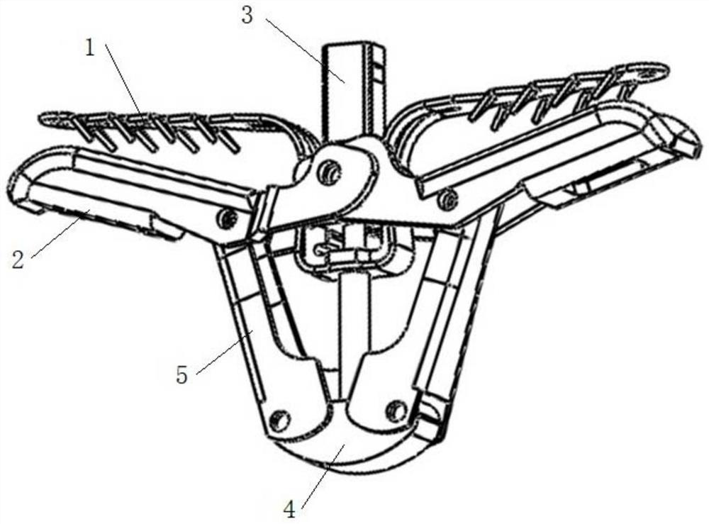
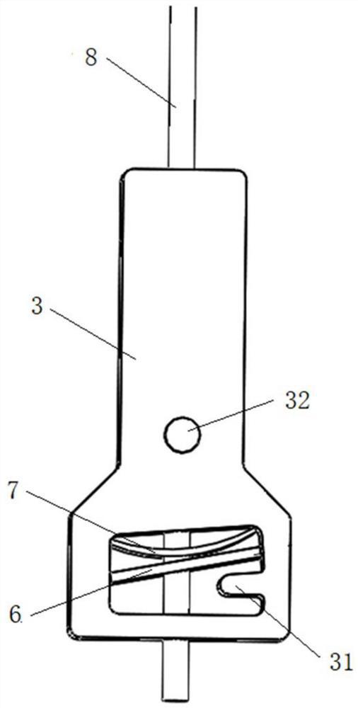
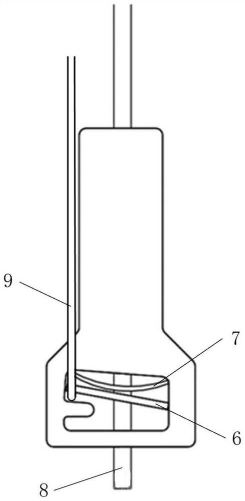
[0032] Such as Figure 1 to Figure 4 As shown, the present embodiment provides a valve clamping system, including an adjustment mechanism and a locking mechanism. Wherein the adjustment mechanism includes a proximal clip 1, a distal clip 2, a central seat body 3 and a base body, the proximal clip 1 is clamped on the central seat 3, and the proximal clip 1 has elasticity, and the distal clip 2 Rotately connected to the central seat body 3 and the base body to approach or stay away from the proximal clip 1, the central seat body 3 has a receiving cavity, and the side wall of the central seat body 3 is provided with relative piercing holes; the locking mechanism includes a fixed piece A6, the fixed piece B7, the push rod 8 and the control piece 9, the fixed piece A6 and the fixed piece B7 are arranged in the accommodating cavity against each other, the push rod 8 is located in the accommodating cavity and passes through the fixed piece A6 and the fixed piece B7 and is connected t...

Embodiment 2

[0050] This embodiment discloses a valve clamping system. The valve clamping system in this embodiment is different from the valve clamping system in Embodiment 1 in that: Figure 5 and Figure 6 As shown, at least the fixed piece B7 is an elastic piece, and the fixed piece B7 is configured such that the fixed piece A6 abuts against the stop protrusion 31 and is located at the first position, and the control member 9 is away from the push rod 8 at one side of the stop protrusion 31 The side bypasses the fixing piece A6 and the fixing piece B7, and pulling the control member 9 can make the fixing piece A6 not in the first position. Optionally, both the fixed piece B7 and the fixed piece A6 are elastic pieces, but when the fixed piece A6 is subjected to gravity and the elastic force exerted by the fixed piece B7, it is different from that in the first embodiment, as Figure 5 As shown, when the control member 9 is loosened, the fixed piece A6 cannot be horizontally placed in th...


PUM


Abstract

The invention relates to the field of medical instruments, and discloses a valve clamping system, which comprises an adjusting mechanism and a locking mechanism; the adjusting mechanism comprises a near-end clamping piece, a far-end clamping piece, a central seat body and a base body; the near-end clamping piece is clamped to the central seat body; the far-end clamping piece is rotationally connected to the central seat body and the base body so as to be close to or away from the near-end clamping piece; the central seat body is provided with a containing cavity; opposite penetrating holes are formed in the side wall of the central seat body; the locking mechanism comprises a fixing piece A, a fixing piece B, a pushing rod and a control piece; the fixing piece A and the fixing piece B are arranged in the containing cavity in a mutual abutting mode; the pushing rod is located in the containing cavity and penetrates through the fixing piece A and the fixing piece B to be connected to the base body; and the control piece and the fixing piece B are jointly configured to adjust the position of the fixing piece A in the containing cavity. Therefore, a valve can be stably clamped; the valve clamping system is simple to operate; and surgical risks can be reduced.

Description

technical field [0001] The invention relates to the field of medical devices, in particular to a valve clipping system. Background technique [0002] The tricuspid valve is located in the opening between the right atrium and right ventricle. The tricuspid valve opens to allow blood from the right atrium to fill the right ventricle, and when the right ventricle contracts to pump blood into the lungs, the tricuspid valve closes to prevent blood from flowing back into the right atrium. When the tricuspid valve does not close completely, some blood leaks through the tricuspid valve back into the right atrium each time the right ventricle contracts, known as tricuspid regurgitation. [0003] In recent years, the transcatheter interventional treatment of tricuspid regurgitation has become a research focus and difficulty in the field of heart valve disease treatment. The current valve interventional therapy technology is based on the principle of edge-to-edge surgery to deliver t...

Claims


Application Information

Patent Timeline
Patent Type & Authority Applications(China)
IPC IPC(8): A61F2/24
CPCA61F2/2442A61F2/246A61F2/2466
Inventor 王森宋睿王智琛戴志豪黄中嵘
Owner SHANGHAI SHENQI MEDICAL TECH CO LTD
Why Eureka
Try Eureka