A method and device for multi-axis collaborative blind milling of printed circuit boards

A technology for printed circuit boards and circuit boards, which is used in milling machine equipment, manufacturing tools, and comprehensive factory control. Positioning speed and paste speed, low cost, and the effect of improving efficiency

Active Publication Date: 2022-06-03
湖南省方正达电子科技有限公司
View PDF0 Cites 0 Cited by
  • Summary
  • Abstract
  • Description
  • Claims
  • Application Information

AI Technical Summary

Problems solved by technology

In the mass production of printed circuit boards, 4-axis or 6-axis milling machines are generally used to process step grooves, and the height of the milling cutters on each axis on a multi-axis milling machine is limited by the assembly accuracy of the machine tool itself, or due to the thickness of the processed circuit board itself. Subtle differences will lead to inconsistent step groove depths processed in batches, and the difference in depth control accuracy is often difficult to coordinate. It is impossible to achieve the groove depth (or excess thickness) accuracy of products produced by each axis to meet the requirements of + / -0.1mm
However, if the single-axis operation is adopted, although the groove depth can be guaranteed to be uniform, the production efficiency of the operation is low and the production capacity is wasted.
There is currently no better way to solve this problem

Method used


Image

  • A method and device for multi-axis collaborative blind milling of printed circuit boards
  • A method and device for multi-axis collaborative blind milling of printed circuit boards
  • A method and device for multi-axis collaborative blind milling of printed circuit boards

Examples


Embodiment Construction

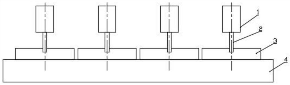
[0044] Wherein, the upper surface of the backing plate 5 can be flattened to form a groove shape, so that the circuit board is fixed on the bottom surface of the groove;

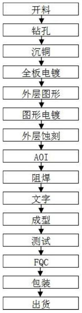
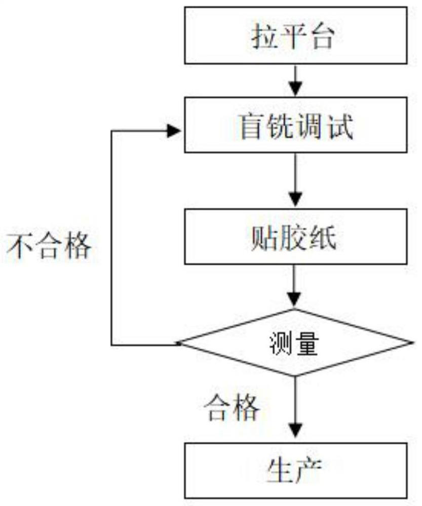
[0055] Mass production: the milling machine that has completed the measurement correction is used for the blind milling batch processing of the circuit board.

[0057] As a preferred embodiment of the above method, the thickness of the adhesive tape is 0.1mm.

[0058] As a preferred embodiment of the above method, the backing board 5 is a medium density wood fiber backing board.

[0062] Wherein, the upper end of the sleeve 703 is provided with a connecting seat 701, and the connecting seat 701 is connected with the connecting plate 903 by bolts;

[0063] Wherein, the telescopic mechanism 702 can be an electric push rod or an air cylinder or an oil cylinder;

[0064] Wherein, the two sides of the sleeve 703 are provided with a connecting rod 704, the connecting rod 704 is provided with a rotating shaft 705, and o...


PUM


Abstract

The invention relates to the technical field of printed circuit board processing, in particular to a multi-axis collaborative blind milling method for printed circuit boards, comprising the following processing steps: pulling the platform: laying a backing board on the worktable; The height remains uniform; Blind milling debugging: During the blind milling process, track and measure the depth of each blind groove. When the blind groove meets the depth and accuracy requirements for the first time, the thickness of the backing plate corresponding to the blind groove is used as the reference thickness; Adhesive paper: Measure Calculate the depth difference for the remaining blind slots of the circuit board that do not meet the processing depth requirements, and paste one or more layers of adhesive tape on the corresponding backing plate according to the depth difference; until the blind slots processed under all the spindles have the same depth; Under the condition of making full use of multi-axis joint operation, the present invention still realizes that the precision of product groove depth (or excess thickness) produced by each axis meets the requirement of + / ‑0.1mm, improves production efficiency, reduces production cost, and is easy to operate , Practical and efficient.

Description

Method and device for multi-axis cooperative blind milling of printed circuit board technical field The present invention relates to the technical field of printed circuit board processing, in particular to a multi-axis cooperative blind milling method for printed circuit boards and device. Background technique [0002] A printed circuit board, also known as a printed circuit board, is a provider of electrical connections for electronic components. Multipurpose printed circuit board PCB" to represent. The design of printed circuit boards is mainly layout design, and the main advantage of using circuit boards is to greatly reduce wiring And assembly errors, improve the automation level and production labor rate. According to the number of layers of the circuit board, it can be divided into single-sided, double-sided, Four-layer boards, six-layer boards, and other multi-layer circuit boards. The existing processing flow chart of printed circuit board is shown in Figu...

Claims


Application Information

Patent Timeline
Patent Type & Authority Patents(China)
IPC IPC(8): B23C3/28B23C9/00
CPCB23C3/28B23C9/00Y02P90/02
Inventor 李长生田德琴方笑求沈兴林
Owner 湖南省方正达电子科技有限公司
Why Eureka
Try Eureka