Multidirectional adjustable cast-in-place box girder integral sliding type side mold

A sliding and adjustable technology, which is applied in the fields of formwork/formwork/work frame, on-site preparation of building components, construction, etc., can solve the problem of the removal and erection of side formwork support with long construction period, high safety risk, and impact on box girder construction. progress, etc.

Active Publication Date: 2021-11-02
中铁一局集团(广州)建设工程有限公司 +1
View PDF17 Cites 0 Cited by
  • Summary
  • Abstract
  • Description
  • Claims
  • Application Information

AI Technical Summary

Problems solved by technology

[0003] To sum up, after a single pouring is completed, all the side form supports and side forms need to be dismantled and reassembled. Due to the high safety risk of dismantling at high altitude, and the long period of removal and erection of side form supports, it will affect the construction progress of the box girder. Therefore, there are still room for improvement

Method used


Image

  • Multidirectional adjustable cast-in-place box girder integral sliding type side mold
  • Multidirectional adjustable cast-in-place box girder integral sliding type side mold

Examples


Embodiment Construction

[0025] The following is attached Figure 1-2 The present invention is described in further detail.

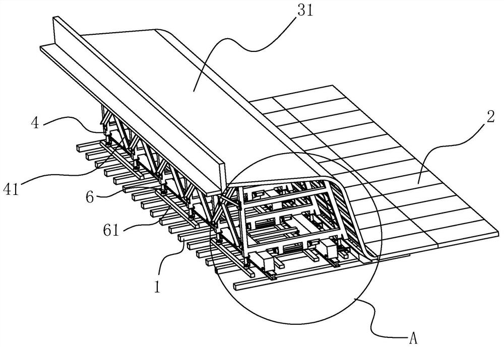
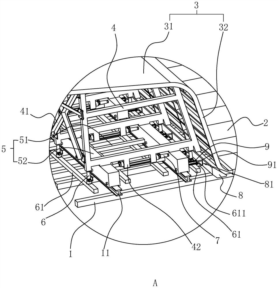
[0026] The embodiment of the invention discloses a multi-directional adjustable cast-in-place box girder integrally sliding side form. A multi-directional adjustable cast-in-place box girder integrated sliding side form includes guide rails, a formwork trolley 5, a formwork support and a side formwork 3. Bottom form 2 is vertically laid on the upper end surface of distribution beam 1, and the formwork support is fixed on the outside of side formwork 3, so that the lower end edge of side formwork 3 is connected with one side of bottom formwork 2. The guide rail is located at one side of the bottom mold 2, and the guide rail extends longitudinally. The formwork trolley 5 slides along the length direction of the guide rail, and the formwork support is erected on the upper surface of the trolley. After the box girder of the upper hole is poured and the concrete has the strength t...


PUM


Abstract

The invention discloses a multidirectional adjustable cast-in-place box girder integral sliding type side mold. The multidirectional adjustable cast-in-place box girder integral sliding type side mold comprises a guide rail longitudinally arranged on one side of the side mold, a mold plate trolley connected with the guide rail in a sliding and clamping mode, a mold plate support erected on the upper end face of the mold plate trolley and a side mold plate fixed to the mold plate support; and the lower end of the side mold plate is connected with one side of a bottom mold, and the mold plate trolley supports the mold plate support and the side mold plate and slides in the extending direction of the guide rail. The side mold has the effects of reducing risks and shortening the box girder construction progress.

Description

technical field [0001] The invention relates to the technical field of box girder construction, in particular to a multi-directional adjustable integral sliding side form of a cast-in-place box girder. Background technique [0002] The cast-in-place box girder is often cast in-situ by the method of full support. When setting up the formwork, the bottom formwork is first laid longitudinally along the distribution beam, and then the side formwork brackets are set up on both sides of the bottom formwork, and then the side forms are fixed on the inside of the side formwork supports. It is usually assembled with bamboo plywood square wood structure or ordinary steel formwork, and the side formwork bracket plays a supporting role on the side formwork. [0003] To sum up, after a single pouring is completed, all the side form supports and side forms need to be dismantled and reassembled. Due to the high safety risk of dismantling at high altitude, and the long period of removal and...

Claims


Application Information

Patent Timeline
IPC IPC(8): E04G13/04
CPCE04G13/04
Inventor 赵佩力陈一钊马文勇魏琨田震
Owner 中铁一局集团(广州)建设工程有限公司
Why Eureka
Try Eureka