Special protective cover for turning and milling composite machine tool

A compound machine tool, turning and milling technology, applied in maintenance and safety accessories, metal processing machinery parts, metal processing equipment, etc., can solve the problems of time-consuming and laborious production needs, inconvenient movement or adjustment, operator injury, etc., to save time in operation The effect of labor saving, simple and efficient installation and convenient operation

Inactive Publication Date: 2021-11-02
金华市小狸新材料科技有限责任公司
View PDF0 Cites 0 Cited by
  • Summary
  • Abstract
  • Description
  • Claims
  • Application Information

AI Technical Summary

Problems solved by technology

[0004] The purpose of the present invention is to provide a special protective cover for turning and milling machine tools to solve the problem in the above-mentioned background technology that after the installation of the current turning and milling machine tools is completed, the peripheral protective cover is still required when it is processed. The splashing of waste materials will cause certain injuries to the operators. The current protective cover is installed on the side of the machine tool, which will have a certain impact on the machine tool itself. At the same time, it will bring a certain impact when moving or adjusting It is inconvenient, and when opening and closing the door, it is necessary to manually pull or push the operation, which makes it time-consuming and labor-intensive, which is not conducive to the current production needs.

Method used


Image

  • Special protective cover for turning and milling composite machine tool
  • Special protective cover for turning and milling composite machine tool
  • Special protective cover for turning and milling composite machine tool

Examples


Embodiment Construction

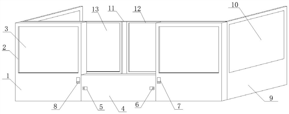
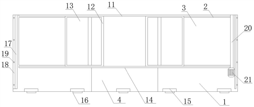
[0028] see Figure 1-2 , in an embodiment of the present invention, a special shield for turning and milling compound machine tools, including a main support plate 1, an observation window 2 is provided on the side of the main support plate 1, and a transparent plate 3 is horizontally clamped on the inner side of the observation window 2 , the number of main support plates 1 is two, and the two main support plates 1 are arranged parallel to each other vertically and symmetrically, the specifications and sizes of the two main support plates 1 are kept consistent, and the observation window 2 is set horizontally on the main support One side of the plate 1 is close to the top surface, and the transparent plate 3 is made of a heat-resistant transparent material. The main support plate 1 is horizontally connected to the connecting bottom plate 4, and one side of the connecting bottom plate 4 is horizontally symmetrical. Toggle the groove 5, the connecting bottom plate 4 is set hori...


PUM


Abstract

The invention discloses a special protective cover for a turning and milling composite machine tool, and relates to the field of turning and milling machine tools. The special protective cover comprises main supporting plates, wherein the side edges of the main supporting plates are provided with observation windows, the inner side edges of the observation windows are horizontally connected with transparent plates in a clamped mode, and the side edges between the main supporting plates are horizontally connected with connecting bottom plates in a butt joint mode; transverse shifting grooves are horizontally and symmetrically formed in side edges of the connecting bottom plates, shifting plates are inserted into the inner side edges of the transverse shifting grooves, vertical shifting grooves are vertically formed in side edges of the main supporting plates, moving blocks are inserted into the inner side edges of the vertical shifting grooves, and supporting side plates are in butt joint with side edges of the main supporting plates; the side edges of the supporting side plates are horizontally connected with side transparent windows in a clamped mode, and side edges of the main supporting plates are horizontally connected with top sliding rails in a bolted mode. The device is designed to be split, the structure is simple, operation is convenient, installation is easy, convenient and efficient by adopting a buckle connection mode, and meanwhile, time and labor are saved by adopting an electric adjusting mode.

Description

technical field [0001] The invention relates to the technical field of turning and milling machine tools, in particular to a special protective cover for turning and milling compound machine tools. Background technique [0002] The application of numerical control technology has not only brought revolutionary changes to the traditional manufacturing industry, making the manufacturing industry a symbol of industrialization, but also with the continuous development of numerical control technology and the expansion of application fields, it has a great impact on some important industries (IT, automobile, etc.) of the national economy and people's livelihood. , light industry, medical care, etc.) is playing an increasingly important role, because the digitization of equipment required by these industries has become a major trend of modern development. [0003] For the current turning and milling machine tools, after the installation is completed, the peripheral protective cover ...

Claims


Application Information

Patent Timeline
Patent Type & Authority Applications(China)
IPC IPC(8): B23Q11/08
CPCB23Q11/08
Inventor 李斌
Owner 金华市小狸新材料科技有限责任公司
Why Eureka
Try Eureka