Slide rail mechanism for providing pre-tightening force to prevent automatic opening when drawer is closed
An automatic opening and pre-tightening technology, which is applied in drawers, electric alarm locks, building structures, etc., can solve the problems of damage to drawers, automatic opening of drawers, contact, etc., and achieve the effect of simple operation
- Summary
- Abstract
- Description
- Claims
- Application Information
AI Technical Summary
Problems solved by technology
Method used
Image
Examples
Embodiment 1
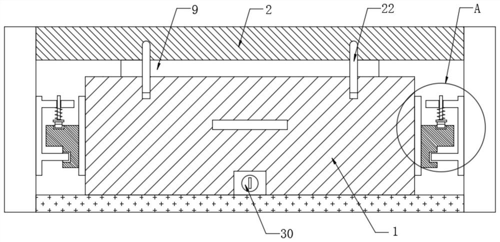
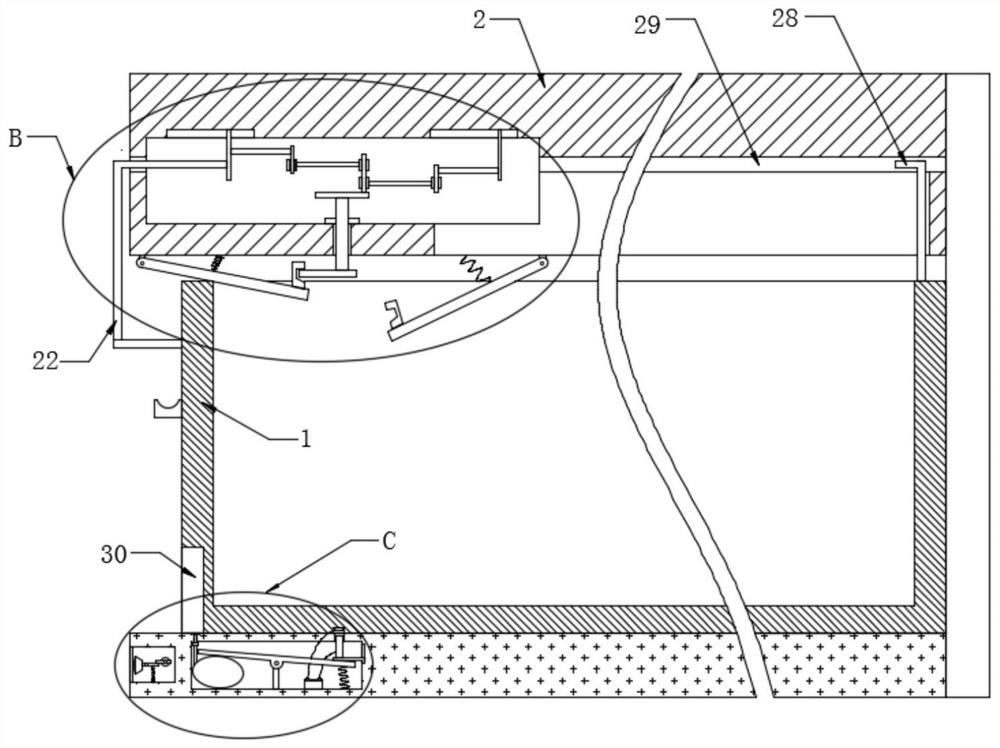
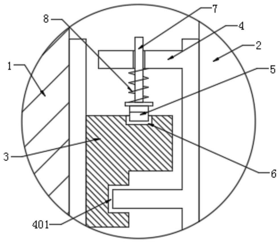
[0027] refer to Figure 1-6, a slide rail mechanism that provides pre-tightening force to prevent automatic opening when the drawer is closed, including a drawer body 1, a handle is fixedly installed on the front end of the drawer body 1, and a handle groove is opened on the handle, and the outside of the drawer body 1 is inserted There is a frame 2, and the left and right ends of the drawer body 1 are fixedly equipped with connecting bars 3, and the sides of the connecting bars 3 that are far away from each other are provided with fixing bars 4, and the ends of the fixing bars 4 that are far away from each other are fixedly installed on the inner wall of the frame 2, so One end of the connecting strips 3 far away from each other is provided with a chute 401 corresponding to the fixing strip 4, the connecting strip 3 is slidably connected to the fixing strip 4, the drawer body 1 is slidably connected to the frame 2, and the upper end of the connecting strip 3 is inserted with a...
Embodiment 2
[0030] refer to Figure 1-6 , in this embodiment, it is basically the same as Embodiment 1, and more optimally, the inner top of the frame 2 is hinged with an anti-jamming plate 1 9, and the rear side of the anti-jamming plate 1 9 is provided with an anti-jamming plate 2 10, and the anti-jamming plate 2 The upper end of the second 10 is hinged with the frame 2, and the upper end of the anti-jamming plate 9 and the anti-jamming plate 2 10 is fixedly installed with a spring 2 11, and the upper end of the spring 2 11 is fixedly installed with the frame 2, and the anti-jamming plate 1 9 and the anti-jamming plate 2 are fixedly installed. 10 upper ends close to each other are fixedly equipped with a draw-in slot plate 12, and on the anti-clamp plate-9, the draw-in slot plate 12 is inserted with a draw bar 13, and the draw bar 13 upper end is fixedly equipped with a rotating shaft 14, and the upper side of the rotating shaft 14 Inserted on the frame 2, a bearing 15 is fixedly instal...
Embodiment 3
[0033] refer to Figure 1-6 , in this embodiment, it is basically the same as Embodiment 1, and more optimally, a drawer lock 30 is fixedly installed on the lower side of the front end of the drawer body 1, an airbag 31 is fixedly connected inside the bottom end of the frame 2, and an airbag 31 is fixedly installed on the upper end of the airbag 31. A connecting pipe 32, a whistle 40 is fixedly installed on the connecting pipe 32, a piston 33 is inserted at the upper end of the connecting pipe 32, and the upper end of the piston 33 fits the drawer lock 30 and the drawer body 1, and the upper side of the airbag 31 is provided with a rotating plate 34, The airbag 31 is attached to the rotating plate 34, the middle part of the lower end of the rotating plate 34 is hinged with the frame 2, and the rear side of the lower end of the rotating plate 34 is fixedly equipped with a spring three 35, the lower end of the spring three 35 is fixedly installed inside the frame 2, and the upper...
PUM
 Abstract
Description
Claims
Application Information
 - Generate Ideas
- Intellectual Property
- Life Sciences
- Materials
- Tech Scout
- Unparalleled Data Quality
- Higher Quality Content
- 60% Fewer Hallucinations
Browse by: Latest US Patents, China's latest patents, Technical Efficacy Thesaurus, Application Domain, Technology Topic, Popular Technical Reports.
© 2025 PatSnap. All rights reserved.Legal|Privacy policy|Modern Slavery Act Transparency Statement|Sitemap|About US| Contact US: help@patsnap.com


