
Filler sucking and discharging overhead crane for graphite refining

A technology of filler and graphite, applied in the direction of charge, furnace, charge composition/state, etc., can solve the problems of increasing the cooling burden of the suction crane, reducing the cooling efficiency, prolonging the cooling time, etc., to expand the scope of application of the suction temperature, Improve the cooling effect and ensure the effect of suction

Inactive Publication Date: 2021-10-29
万基控股集团石墨制品有限公司
View PDF0 Cites 1 Cited by
  • Summary
  • Abstract
  • Description
  • Claims
  • Application Information

AI Technical Summary

Problems solved by technology

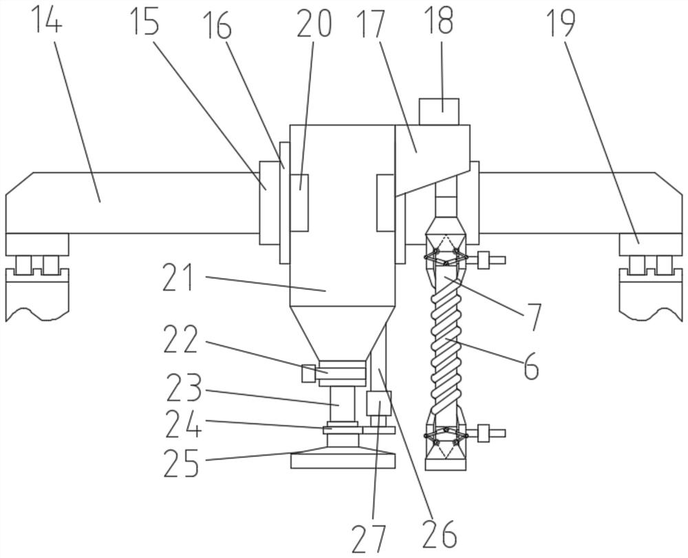
[0002] At present, the suction and laying operations of filler materials in graphite refining are generally carried out by suction and unloading cranes. The existing suction and unloading cranes are generally equipped with corresponding suction and unloading systems, cooling systems, dust removal systems, electric Control system, etc., can directly absorb the red hot material, can improve the temperature, speed and dust removal effect of the material, and then improve the efficiency of furnace loading. When unloading, the filling material in the unloading bin will pass through the discharge pipe Fall naturally, and stack them in a specific place; however, when the temperature of the filling material is too high, it will increase the cooling burden of the suction crane itself, reduce the cooling efficiency, and prolong the cooling time. Improvements are made on the basis of the system to meet more material suction needs; in addition, in the past, in the process of unloading and spreading, because the length, width and position of the outlet of the unloading pipe are fixed, and the width of the spreading site is variable, often It is necessary to control the suction crane to move back and forth multiple times, which reduces the efficiency of unloading

Method used


Image

  • Filler sucking and discharging overhead crane for graphite refining
  • Filler sucking and discharging overhead crane for graphite refining
  • Filler sucking and discharging overhead crane for graphite refining

Examples


Embodiment Construction

[0026] The technical solutions of the present invention will be described below in conjunction with the accompanying drawings in the embodiments of the present invention. In the description, it should be understood ", "Right" and other indicated orientations or positional relationships are only corresponding to the drawings of the present invention. In order to facilitate the description of the present invention, they do not indicate or imply that the referred device or element must have a specific orientation:

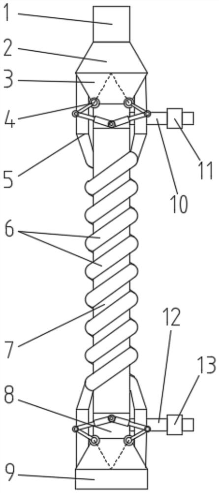
[0027] combined with Figure 1-7 The described graphite-refined filling material suction and discharge crane comprises a main beam 14, a trolley frame 15, a discharge bin 21, a discharge pipe 23 and a buffer bin 17, and two ends of the main beam 14 are installed respectively. A cart operating mechanism 19 can drive the main beam 14 to move laterally along it through the cart operating mechanism 19. The trolley frame 15 is installed on the main beam 14 and can move axi...


PUM


Abstract

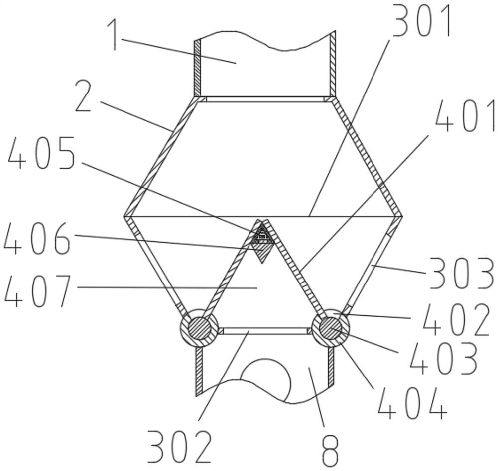
The invention discloses a filler sucking and discharging overhead crane for graphite refining, and relates to the technical field of graphite electrode production. The filler sucking and discharging overhead crane for graphite refining comprises a main beam, a trolley frame, a discharging bin, a discharging pipe and a buffering bin, the discharging bin is connected with the discharging pipe, a spreading head is mounted at the lower end of the discharging pipe, and an exhaust fan and a sucking pipe are arranged at the upper end and the lower end of the buffering bin respectively; a rotary support is arranged between the discharging pipe and the spreading head; two two-position four-way valves are installed at the two ends of the sucking pipe respectively, each four-way valve body is provided with a main passageway, an auxiliary passageway and two side passageways, two semicircular pipes are arranged outside the sucking pipe, the lower ports of the two semicircular pipes correspondingly communicate with the two side passageways of the four-way valve body at the bottom end of the sucking pipe respectively, and the upper ports of the two semicircular pipes correspondingly communicate with two side passageways of the four-way valve body at the top end of the sucking pipe respectively; and a cold water outlet pipe and a cold water inlet pipe are respectively arranged at the top end and the bottom end of the sucking pipe. The sucking and discharging overhead crane not only can greatly widen the temperature application range of material sucking, but also can adapt to material spreading sites with various widths, and the discharging efficiency is improved.

Description

technical field [0001] The invention relates to the technical field of graphite electrode production, in particular to a filling material suction and discharge crane for graphite refining. Background technique [0002] At present, the suction and laying operations of filler materials in graphite refining are generally carried out by suction and unloading cranes. The existing suction and unloading cranes are generally equipped with corresponding suction and unloading systems, cooling systems, dust removal systems, electric Control system, etc., can directly absorb the red hot material, can improve the temperature, speed and dust removal effect of the material, and then improve the efficiency of furnace loading. When unloading, the filling material in the unloading bin will pass through the discharge pipe Fall naturally, and stack them in a specific place; however, when the temperature of the filling material is too high, it will increase the cooling burden of the suction cran...

Claims


Application Information

Patent Timeline
Patent Type & Authority Applications(China)
IPC IPC(8): F27D3/00
CPCF27D3/00F27D2003/0051F27M2001/04
Inventor 安治强李喜锋詹宁宁王照阳马志华宋志昂郭红松夏百元张冰介龙刚
Owner 万基控股集团石墨制品有限公司
Learn More