


Quick Research
Generate reliable direction feasibility study reports for your R&D in just a few steps.

Technical Q&A
Discover and master advanced knowledge NOW. Basics, ideas, possibilities, all at once.

Find Solutions
As an expert in R&D theories, this can generate solutions to your technical problems instantly.

Evaluate Feasibility
Analyze your overall solution with one click, know your potential R&D risks in advance.

Monitor Landscape
Get weekly tech updates, stay abreast of the latest tech innovations and key insights.
A kind of indoor decoration stone laying equipment and process
An interior decoration and stone technology, applied in the direction of construction and building structure, can solve the problems of jamming, inability to take mortar at a fixed point, easy accumulation of additives, etc., and achieve the effect of consistent mortar volume.
- Summary
- Abstract
- Description
- Claims
- Application Information
AI Technical Summary
Problems solved by technology
Method used
Image

Examples
Embodiment 1
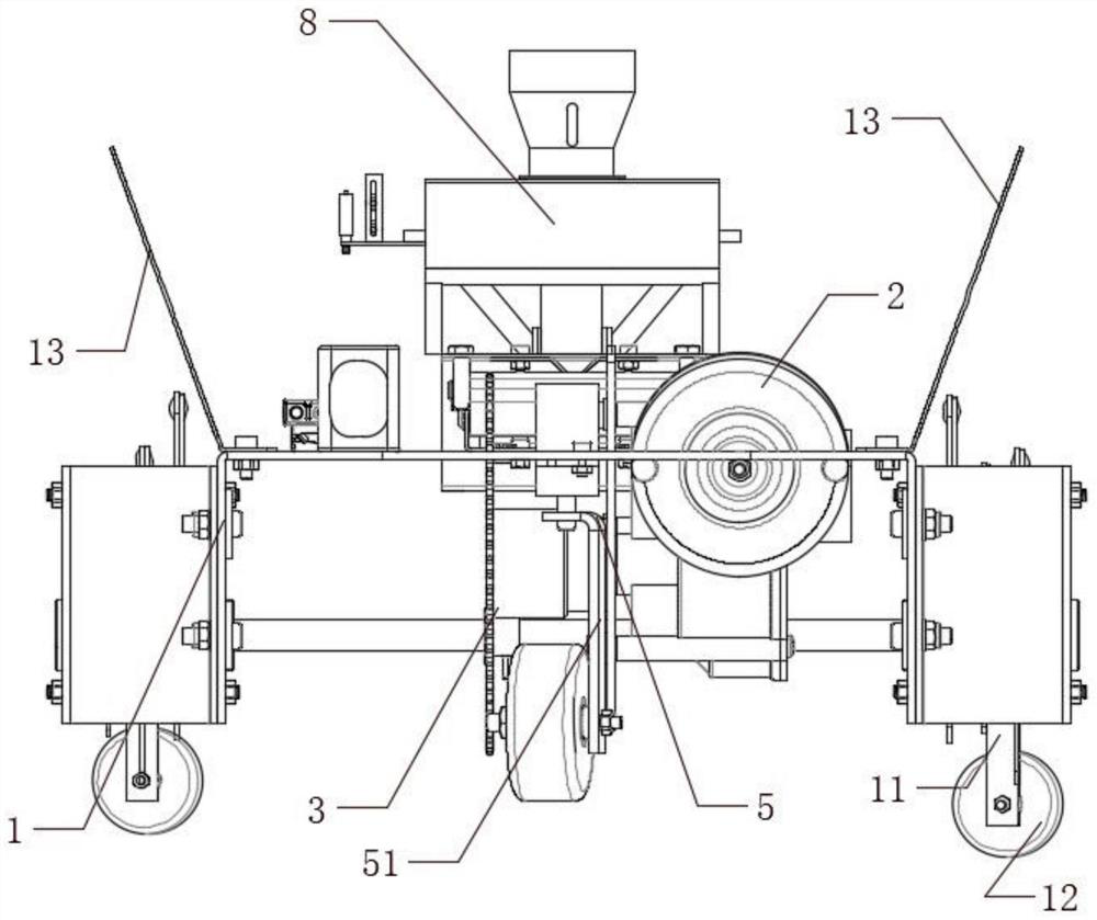
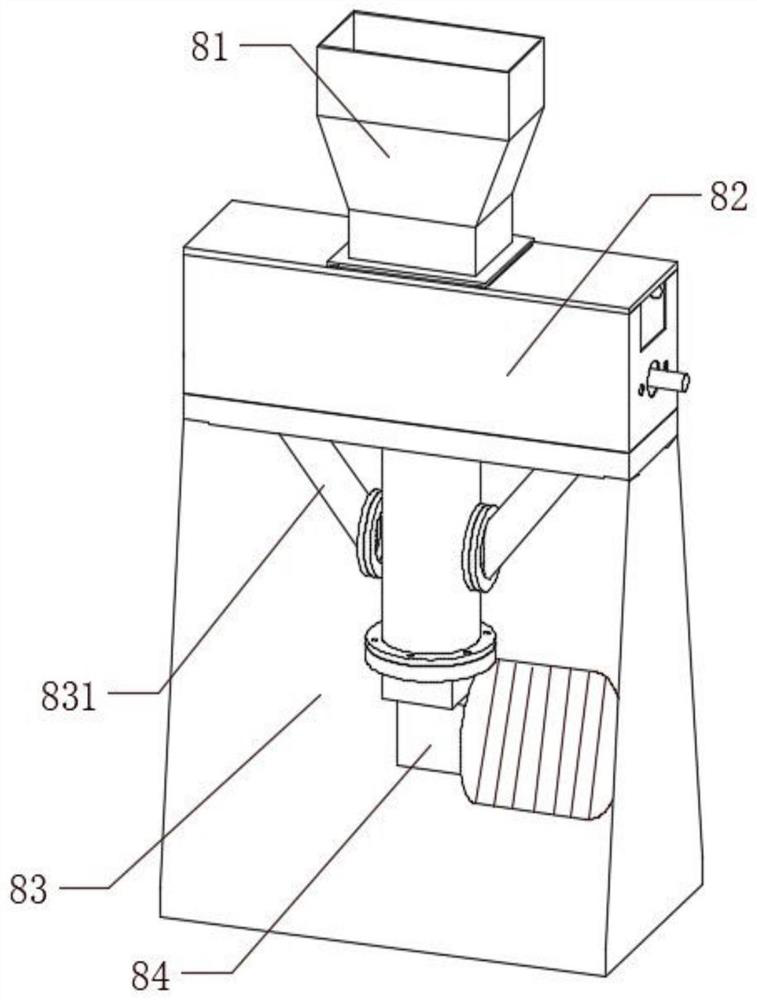
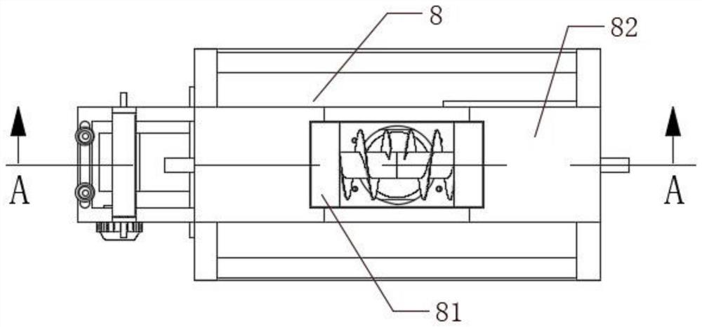
[0051] An indoor decorative stone laying equipment, comprising a driving mechanism 1, a power mechanism 2 and a cutting mechanism 3, the power mechanism 2 and the cutting mechanism 3 are arranged at the lower end of the driving mechanism 1 and connected with the driving mechanism 1, and the upper end of the driving mechanism 1 is also provided with The brick body sizing device 8, the brick body sizing device 8 is a guide cover body 81, a material adding part 82, and a mixing part 83 from top to bottom. The first material unit 821 and the second material pushing unit 822 rotate to stir the material and push it to both sides. The outside of the mixing part 83 is provided with a connecting cylinder 831 and a valve body 832 for controlling the flow of the material. The mixing part 83 passes through the connecting cylinder 831. It communicates with the feeding part 82, and the mixing part 83 is provided with a mixing unit 833. When the mixing unit 833 stirs and pushes the material u...
Embodiment 2
[0064] Embodiment As a further improvement of the previous embodiment, as Figure 1-7 As shown, a kind of indoor decorative stone laying equipment of the present invention comprises a driving mechanism 1, a power mechanism 2 and a cutting mechanism 3, the power mechanism 2 and the cutting mechanism 3 are arranged at the lower end of the driving mechanism 1 and connected with the driving mechanism 1, and the driving mechanism The upper end of 1 is also provided with a brick body sizing device 8, and the brick body sizing device 8 is a guide cover body 81, a material adding part 82, and a mixing part 83 from top to bottom. The second material unit 822, the first material pushing unit 821 and the second material pushing unit 822 rotate to stir the material and push it to both sides. The outside of the mixing part 83 is provided with a connecting cylinder 831 and a valve body 832 for controlling the flow of the material. The mixing part 83 communicates with the feeding part 82 thr...
PUM
 Abstract
Description
Claims
Application Information
 - R&D Engineer
- R&D Manager
- IP Professional
- Industry Leading Data Capabilities
- Powerful AI technology
- Patent DNA Extraction
Browse by: Latest US Patents, China's latest patents, Technical Efficacy Thesaurus, Application Domain, Technology Topic, Popular Technical Reports.
© 2024 PatSnap. All rights reserved.Legal|Privacy policy|Modern Slavery Act Transparency Statement|Sitemap|About US| Contact US: help@patsnap.com