
Tank cover of plating tank and electroplating production line

A technology of plating tank and tank cover, applied in the direction of plating tank, etc., can solve the problems of unfavorable overall efficiency of electroplating production line, insufficient automation of tank cover, lower opening and closing efficiency of tank cover, etc., so as to reduce opening and closing time and manual intervention, improve Electroplating efficiency, simple structure effect

Pending Publication Date: 2021-10-29
WUXI XINGYI INTELLIGENT ENVIRONMENT EQUIP CO LTD
View PDF0 Cites 0 Cited by
  • Summary
  • Abstract
  • Description
  • Claims
  • Application Information

AI Technical Summary

Problems solved by technology

[0003] At present, the tank cover of the plating tank is designed as a whole, with a bulky structure, and can only be opened and closed as a whole, resulting in low opening and closing efficiency, and difficulty in early assembly and later maintenance
At the same time, the automation degree of the existing tank cover is not enough, and manual intervention is required for mechanical opening and closing, which further reduces the opening and closing efficiency of the tank cover, which is not conducive to improving the overall efficiency of the electroplating production line

Method used


Image

  • Tank cover of plating tank and electroplating production line
  • Tank cover of plating tank and electroplating production line
  • Tank cover of plating tank and electroplating production line

Examples


Embodiment Construction

[0048] In order to make the technical problems solved by the present invention, the technical solutions adopted and the technical effects achieved clearer, the technical solutions of the present invention will be further described below in conjunction with the accompanying drawings and through specific implementation methods. It should be understood that the specific embodiments described here are only used to explain the present invention, but not to limit the present invention. In addition, it should be noted that, for the convenience of description, only the parts related to the present invention are shown in the drawings but not all of them.

[0049] In the description of the present invention, unless otherwise clearly specified and limited, the terms "connected", "connected" and "fixed" should be understood in a broad sense, for example, it can be a fixed connection, a detachable connection, or an integrated ; It can be a mechanical connection or an electrical connection;...


PUM


Abstract

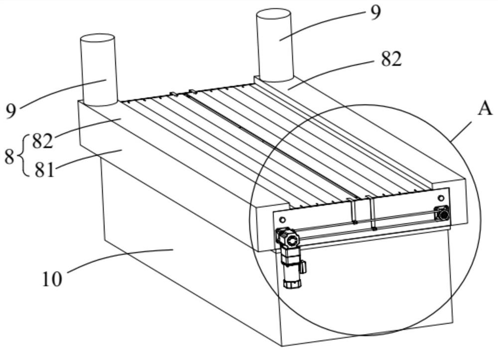
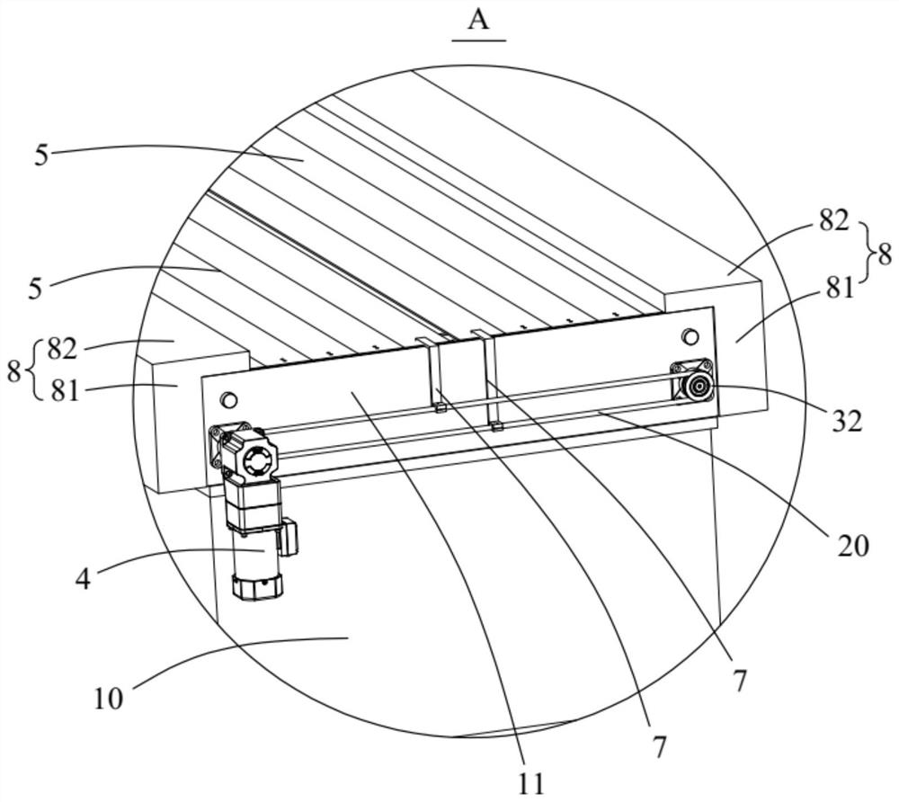
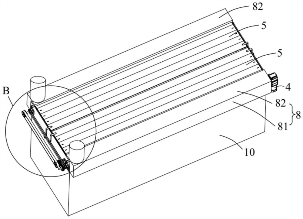
The invention relates to the technical field of electroplating production lines, and discloses a tank cover of a plating tank and an electroplating production line. The tank cover of the plating tank comprises a first supporting plate, a second supporting plate, a main shaft, an auxiliary shaft, a driving piece and roller shutters, and the first supporting plate and the second supporting plate are oppositely arranged on the two sides of the opening end of the plating tank in the length direction. The two ends of the main shaft are rotationally arranged on the first sides, in the width direction of the plating tank, of the first supporting plate and the second supporting plate correspondingly. The two ends of the auxiliary shaft are rotationally arranged on the second sides, in the width direction of the plating tank, of the first supporting plate and the second supporting plate correspondingly. The main shaft and the auxiliary shaft are in transmission connection and have opposite rotation directions. The driving piece is in transmission connection with the main shaft. The fixed ends of the two roller shutters are respectively wound on the main shaft and the auxiliary shaft. When the main shaft and the auxiliary shaft rotate synchronously, the free ends of the two roller shutters abut against each other or are far away from each other, so that the opening end of the plating tank is blocked or opened. The tank cover of the plating tank is designed in a split mode, opening and closing are flexible, and the opening and closing efficiency is improved.

Description

technical field [0001] The invention belongs to the technical field of electroplating production lines, and in particular relates to a tank cover of a plating tank and an electroplating production line. Background technique [0002] The plating tank is an important part of the electroplating production line, mainly used to hold the plating solution and perform electroplating operations. Since the plating solution in some plating tanks is toxic and volatile, it is necessary to set a tank cover to seal the plating tank to ensure the safety and environmental protection requirements of on-site electroplating operations. [0003] At present, the tank cover of the plating tank is designed as a whole, with a bulky structure, and can only be opened and closed as a whole, resulting in low opening and closing efficiency, and difficulty in early assembly and later maintenance. At the same time, the automation degree of the existing tank cover is not enough, and manual intervention is ...

Claims


Application Information

Patent Timeline
Patent Type & Authority Applications(China)
IPC IPC(8): C25D17/02C25D19/00
CPCC25D17/02
Inventor 匡优新陈建林
Owner WUXI XINGYI INTELLIGENT ENVIRONMENT EQUIP CO LTD
Learn More