Mask fastening system and anesthesia airway auxiliary management instrument
A fastening system and mask technology, applied in the field of anesthesiology, can solve problems such as inability to apply to different types of patients, inability to adjust the degree of mask compression at any time, etc., and achieve the effect of preventing air leakage
- Summary
- Abstract
- Description
- Claims
- Application Information
AI Technical Summary
Problems solved by technology
Method used
Image
Examples
specific Embodiment approach 1
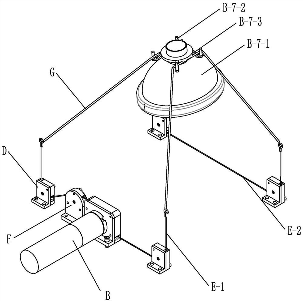
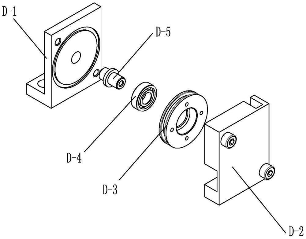
[0015] Specific implementation mode one: combine Figure 1 to Figure 3 Describe this embodiment, this embodiment includes driving system B, multiple transmission systems, mask B-7, tension rope G and housing C, described driving system B and described multiple transmission systems are installed in described housing In C, the tensioning rope G is buckled on the mask B-7 and extends into the housing C, passes through the multiple transmission systems, and finally the head and the end are all accommodated in the drive system B, The driving system B drives the head and the end of the tensioning rope G to move so that the length of the tensioning rope G outside the driving system B changes, and then converts the tensioning rope G to fasten the mask B The magnitude of the force of -7 varies; when tightened, the tensile force that the tension rope G experiences on the parts other than the drive system B is the same. Because the suffered pulling force is all the same everywhere on th...
specific Embodiment approach 2
[0016] Specific implementation mode two: combination figure 1 To describe this embodiment, the multiple transmission systems of this embodiment are installed in the housing C in a rectangular array, and the mask B-7 is located above the middle of the rectangular array. Such setting further makes the tensioning rope G symmetrically arranged with respect to each pulling force on the mask B-7, ensuring the mask pressing effect. Other components and connections are the same as those in the first embodiment.
specific Embodiment approach 3
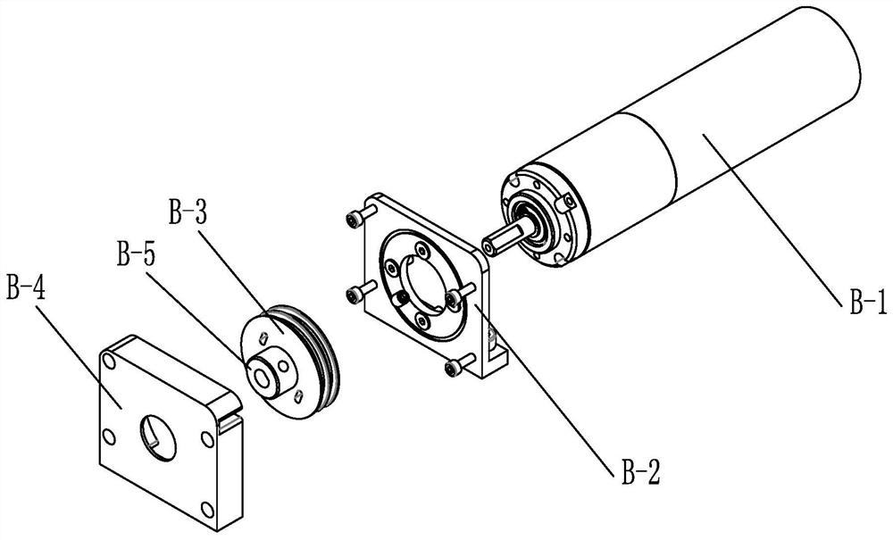
[0017] Specific implementation mode three: combination image 3 To illustrate this embodiment, the drive system B of this embodiment includes a fastening motor B-1, a fastening motor seat B-2 and a double slot guide wheel B-3, and the fastening motor B-1 is installed on the On the fastening motor seat B-2, the double wire groove guide wheel B-3 is fixedly connected to the output shaft of the fastening motor B-1; the double wire groove guide wheel B-3 can accommodate the tension rope at the same time The head end of G, when the fastening motor B-1 is working, drives the double wire slot guide wheel B-3 to rotate, thereby tightening or loosening the head end of the tension rope G at the same time, so as to realize the length change of the wire rope G. This structure saves the internal space, and ensures the same stress on the head and end of the tension rope G, which is beneficial to improve the service life of the steel wire rope G.
[0018] Preferably, the drive system B also...
PUM
 Abstract
Description
Claims
Application Information
 - R&D
- Intellectual Property
- Life Sciences
- Materials
- Tech Scout
- Unparalleled Data Quality
- Higher Quality Content
- 60% Fewer Hallucinations
Browse by: Latest US Patents, China's latest patents, Technical Efficacy Thesaurus, Application Domain, Technology Topic, Popular Technical Reports.
© 2025 PatSnap. All rights reserved.Legal|Privacy policy|Modern Slavery Act Transparency Statement|Sitemap|About US| Contact US: help@patsnap.com


