
Television backlight control logic demonstration method, device and equipment and storage medium

A technology of backlight control and demonstration method, which is applied to static indicators, instruments, etc., can solve the problems such as the limitation of the backlight logic demonstration environment and cannot be fully displayed, and achieve the effect of improving the demonstration effect, ensuring the demonstration effect, and reducing the requirements of the environment.

Pending Publication Date: 2021-10-26
SHENZHEN SKYWORTH RGB ELECTRONICS CO LTD
View PDF4 Cites 1 Cited by
  • Summary
  • Abstract
  • Description
  • Claims
  • Application Information

AI Technical Summary

Problems solved by technology

[0005] The main purpose of the present invention is to provide a TV backlight control logic demonstration method, device, equipment and storage medium, aiming to solve the technical problem that the prior art backlight logic demonstration cannot be fully displayed due to environmental restrictions

Method used


Image

  • Television backlight control logic demonstration method, device and equipment and storage medium
  • Television backlight control logic demonstration method, device and equipment and storage medium
  • Television backlight control logic demonstration method, device and equipment and storage medium

Examples


no. 1 example

[0064] Based on the above-mentioned first embodiment, the logic demonstration method for TV backlight control in this embodiment, in the step S20, specifically includes:

[0065] Step S21: Determine backlight brightness information according to the backlight control information.

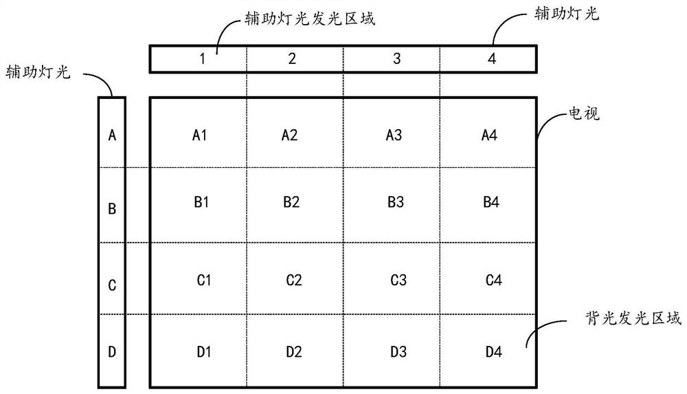
[0066] It should be noted that the brightness information of each light-emitting point may be included in the brightness information of the backlight, or it may be based on image 3 The brightness information of each area shown can be calculated with the brightness information of each area as the smallest unit when the system computing power is insufficient, and the brightness of each luminous area can be the average brightness of the area; but in order to have a better The control effect can also be calculated in the smallest unit of each luminous point, which is a single luminous component in the backlight system.

[0067] In this embodiment, the backlight control matrix data is determined accordi...


PUM


Abstract

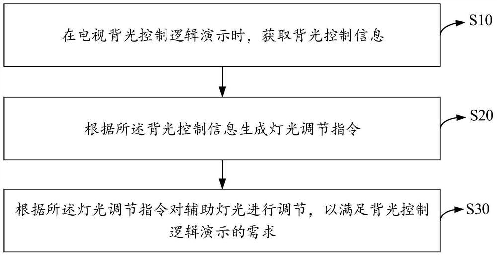
The invention belongs to the technical field of smart televisions, and discloses a television backlight control logic demonstration method, device and equipment and a storage medium. The method comprises the following steps: acquiring backlight control information during television backlight control logic demonstration; generating a light adjusting instruction according to the backlight control information; and adjusting auxiliary light according to the light adjusting instruction so as to meet the requirement of backlight control logic demonstration. According to the method, when the backlight control logic is demonstrated, the light effect is supplemented through the auxiliary light of the television, the display effect can be ensured while the television backlight control logic is demonstrated only by hardware of the television, and due to the fact that the support of ambient light is not needed, the requirement for the environment during television backlight control logic demonstration is reduced, the demonstration cost is reduced, and the demonstration effect of television backlight control logic demonstration is improved.

Description

technical field [0001] The present invention relates to the technical field of smart TVs, in particular to a TV backlight control logic demonstration method, device, equipment and storage medium. Background technique [0002] At present, it is a common practice in the TV industry to optimize the backlight of the TV so that it can better adapt to the current display screen to achieve better display effects and better energy efficiency indicators. As a result, many optimization methods have emerged, such as: adjusting the backlight according to changes in ambient light, adjusting the backlight according to the content of the current screen, or a solution that integrates the above two. [0003] The demonstration of this part during the sales process is also one of the main directions of sales research, allowing users to intuitively and accurately feel the benefits of backlight control on the screen and energy efficiency, which can greatly promote the transaction. At present, t...

Claims


Application Information

Patent Timeline
Patent Type & Authority Applications(China)
IPC IPC(8): G09G3/34
CPCG09G3/3406G09G2320/0626
Inventor 戴宇明
Owner SHENZHEN SKYWORTH RGB ELECTRONICS CO LTD
Learn More