Automatic directional feeding robot for channel steel parts

A robot and material feeding technology, which is applied in the direction of vibrating conveyors, conveyors, conveyor objects, etc., can solve the problems of low efficiency and low degree of automation, and achieve the effects of high efficiency, convenient grasping and welding, and convenient sliding

Pending Publication Date: 2021-10-26
ANHUI UNIVERSITY OF TECHNOLOGY AND SCIENCE +1
View PDF4 Cites 0 Cited by
  • Summary
  • Abstract
  • Description
  • Claims
  • Application Information

AI Technical Summary

Problems solved by technology

[0002] The channel steel is cut into sections of channel steel pieces. On the welding production line, the manipulator needs to grab and weld at fixed points. In order to ensure that the grabbing direction of the manipulator is consistent, it is necessary to feed the channel steel pieces in a directional way. At present, manual pre-sorting is used. To ensure that the direction of the channel steel parts is consistent, the efficiency is low, and the degree of automation is low

Method used


Image

  • Automatic directional feeding robot for channel steel parts
  • Automatic directional feeding robot for channel steel parts
  • Automatic directional feeding robot for channel steel parts

Examples


Embodiment 1

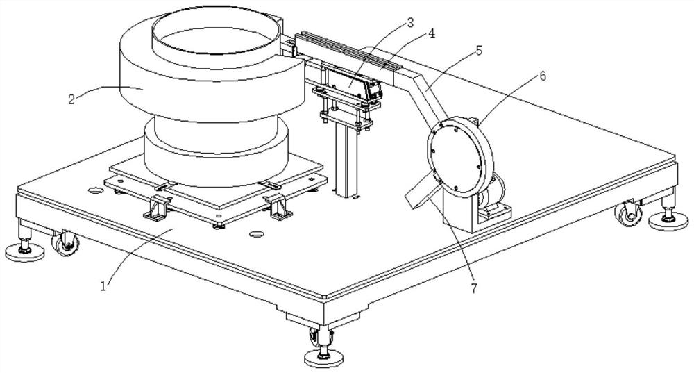
[0038] The automatic channel steel parts directional feeding robot of the present invention pours several channel steel parts into the vibrating plate assembly 2, and under the vibration feeding action of the vibrating plate assembly 2, the channel steel parts enter the conveying guide rail assembly 4 and pass through the miniature The vibration of the oscillator 3 transports forward and falls into the sliding material guide rail 5 .

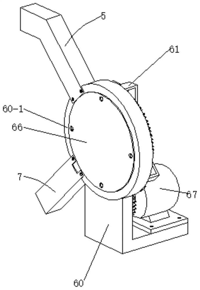
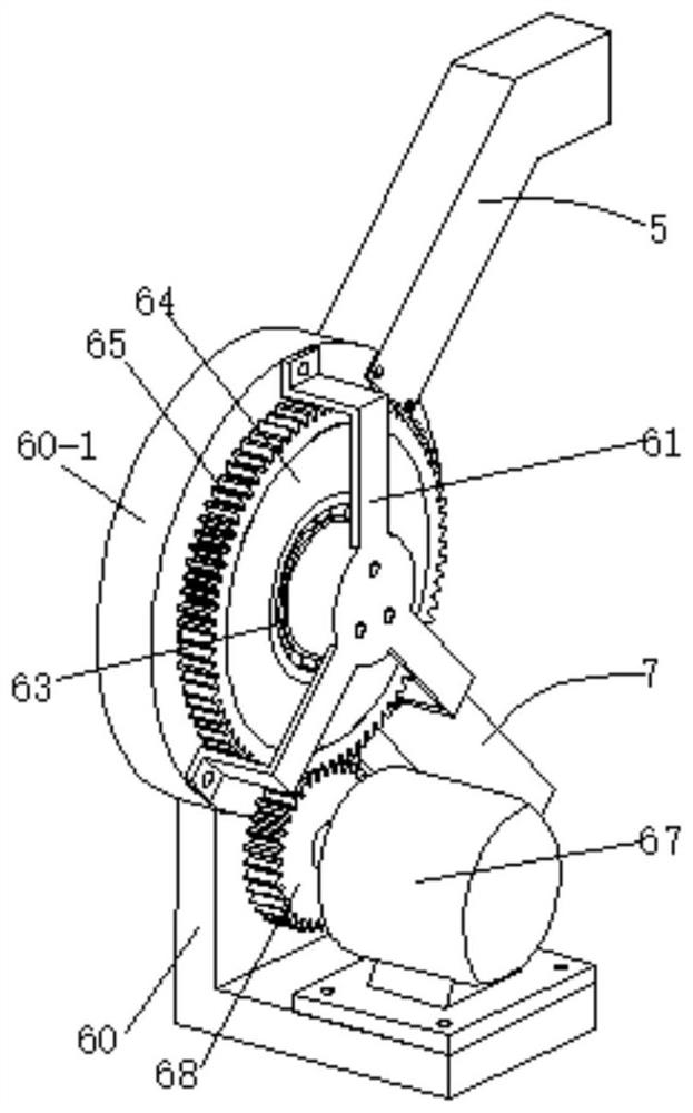
[0039] Then, start the stepper motor 67, and the stepper motor 67 drives the ring gear 65 through the gear 68 to rotate the discharge disc 64 in the fixed ring 60-1 to work at a step angle of 90°.

[0040] When the channel steel piece with the opening facing upwards slides into the discharge groove 64-1, as the discharge plate 64 rotates 90°, the channel steel piece with the upward opening is turned over and buckled on the hanging protrusion 64-2, and at this time The discharge groove 64-1 of the discharge groove 62-1 is aligned with the distrib...

Embodiment 2

[0044]On the basis of Example 1, the inclination angle of the sliding guide rail 5 is +135°; the inclination angle of the feeding guide rail 7 is -135°; the fixed ring 60-1 is provided with a feeding hole 60-2 and the discharge hole 60-3, the feed hole 60-2 communicates with the sliding guide rail 5, and the discharge hole 60-3 communicates with the feed guide rail 7; The three discharge troughs 64-1 correspond to the coordinated work, and on the other hand facilitate the sliding of the channel steel parts.

[0045] The splitter core 62 is provided with a splitter groove 62-1, which ensures the stable discharge of the channel steel piece with the opening facing downward in the sliding material guide rail 5 after it turns over and lands on the hanging protrusion 64-2.

[0046] The discharge tray 64 is provided with a plurality of discharge troughs 64-1, and the discharge trough 64-1 is provided with a material hanging bump 64-2; it ensures that the channel steel piece with the ...


PUM


Abstract

The invention discloses an automatic directional feeding robot for channel steel parts. The automatic directional feeding robot comprises a machine base, a vibration disc assembly, a miniature oscillator, a conveying guide rail assembly, a material sliding guide rail, a directional feeding device and a feeding guide rail, the vibration disc assembly and the miniature oscillator are connected with the machine base, and the conveying guide rail assembly is connected with the upper end of the miniature oscillator; the conveying guide rail assembly is aligned with the discharging hole of the vibration disc assembly,the material sliding guide rail is connected with the upper side of the directional feeding device and is aligned with a discharging port of the conveying guide rail assembly, and the feeding guide rail is connected with the lower side of the directional feeding device, so that automatic directional feeding operation of the channel steel parts is achieved, it is guaranteed that the directions of the channel steel parts are consistent, a mechanical arm can conveniently grab and weld the channel steel parts at a fixed point, and the directional feeding efficiency is high.

Description

technical field [0001] The invention belongs to the technical field of mechanical equipment, in particular, the invention relates to an automatic directional feeding robot for channel steel parts. Background technique [0002] The channel steel is cut into sections of channel steel pieces. On the welding production line, the manipulator needs to grab and weld at fixed points. In order to ensure that the grabbing direction of the manipulator is consistent, it is necessary to feed the channel steel pieces in a directional way. At present, manual pre-sorting is used. To ensure that the direction of the channel steel parts is consistent, the efficiency is low and the degree of automation is low. Contents of the invention [0003] The present invention provides an automatic directional feeding robot for channel steel pieces to solve the problems in the above-mentioned background technology. [0004] In order to achieve the above object, the technical solution adopted by the pr...

Claims


Application Information

Patent Timeline
Patent Type & Authority Applications(China)
IPC IPC(8): B65G27/02B65G47/24B65G11/02B65G29/00
CPCB65G27/02B65G47/24B65G11/023B65G29/00
Inventor 王海涛倪文浩肖平时培成许晶耀孙永久李文瀚陈俊杰刘佳佳赵永康田怡婷宋振鑫王磊李玉龙王留存刘润雨李子辰
Owner ANHUI UNIVERSITY OF TECHNOLOGY AND SCIENCE
Why Eureka
Try Eureka