Panoramic tooth endoscopic shooting device and method

A technology of shooting device and panoramic camera, which is applied in endoscope, dentistry, TV, etc., can solve the problems of not being able to take panoramic pictures, not being able to provide a stable shooting environment, and not being able to observe carefully, so as to reduce shooting time, high economic benefits and The effect of using value and improving shooting stability

Pending Publication Date: 2021-10-26
成都咔哒医疗科技有限公司
View PDF0 Cites 0 Cited by
  • Summary
  • Abstract
  • Description
  • Claims
  • Application Information

AI Technical Summary

Problems solved by technology

[0003] Common dental endoscopes are realized through manual control and mirror reflection, requiring the patient to open their mouth for a long time for the dentist to observe, and due to the limited angle, many parts cannot be observed carefully; even electronic oral endoscopes are mostly The pen-type intraoral camera cannot provide a stable shooting environment and cannot take panoramic pictures

Method used


Image

  • Panoramic tooth endoscopic shooting device and method
  • Panoramic tooth endoscopic shooting device and method
  • Panoramic tooth endoscopic shooting device and method

Examples


Embodiment 1

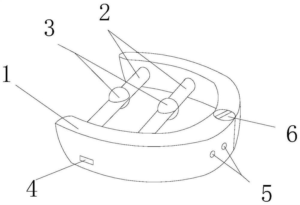
[0027] Such as figure 1 As shown, a panoramic dental endoscopic photographing device includes a U-shaped supporter 1, a connecting piece 2 and a photographing assembly 3, the connecting piece 2 is connected to the U-shaped supporter 1, and the photographing assembly 3 is arranged on the on the connector 2.

[0028] The function of taking a panoramic photo in the oral cavity can be realized by the above structure, the U-shaped support 1 is used to open the oral cavity, the connecting piece 2 fixes the photographing assembly 3 on the U-shaped support 1, and the photographing assembly 3 takes pictures to complete the work; now Some dental endoscopes or oral endoscopes can only be taken by the medical staff, which is very unstable and the shooting efficiency is not high. Any movement of the patient's mouth will cause blurred photos. This design uses a U-shaped The supporter 1 just enhances the stability, and the patient can directly bite the U-shaped supporter 1 to stabilize the ...

Embodiment 2

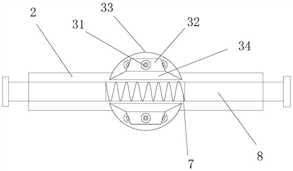
[0040] Based on Example 1, such as figure 2 As shown, in order to make the panoramic dental endoscopic shooting device adapt to the oral cavity of different people, the U-shaped support 1 includes a left wing, a right wing and a hinge 6, and the left wing and the right wing are connected by the hinge 6. In order to cooperate with the hinge 6 , telescopic parts 8 are provided at both ends of the connecting part 2 , and a telescopic part 8 is slidably connected to both sides of the connecting part 2 , and the two telescopic parts 8 are connected by a spring 7 .

[0041] Two groups of the connecting piece 2 and the photographing assembly 3 are arranged, which can improve the photographing efficiency and facilitate proofreading of the synthesized panoramic photos.


PUM


Abstract

The invention discloses a panoramic tooth endoscopic shooting device. The device comprises a U-shaped support, a connecting piece and a shooting assembly, wherein the connecting piece is connected with the U-shaped support, and the shooting assembly is arranged on the connecting piece. By means of the structure, the function of shooting panoramic photos in the oral cavity can be achieved, the U-shaped support is used for opening the oral cavity, the shooting assembly is fixed to the U-shaped support through the connecting piece, and the shooting assembly shoots photos to complete the work. An existing tooth endoscope or oral cavity endoscope can only be held by medical staff for shooting and is unstable and low in shooting efficiency, and shot photos are blurred due to any movement of the patient mouth, however, the stability is exactly enhanced due to the U-shaped support adopted in the design, and the shooting assembly can be stabilized as long as the patient can directly bite the U-shaped supporting device during use.

Description

technical field [0001] The present invention relates to technical fields such as panoramic shooting and dental endoscopic devices, and in particular to a panoramic dental endoscopic shooting device and method. Background technique [0002] The first endoscopes were made of rigid tubes and were invented more than 100 years ago. Although they have gradually improved, they are still not widely used. Later, in the 1950s, endoscopes were made of flexible tubes that could easily bend around the corners of the body. In 1965, Harold Hopkins installed a cylindrical lens on the endoscope to make the field of view clearer. Today's endoscopes usually have two fiberglass tubes, and light enters the body through one of them. The doctor The observation is made through another tube or through a video camera, and some endoscopes even have tiny integrated circuit sensors that feed back what they see to a computer. [0003] Common dental endoscopes are realized through manual control and mi...

Claims


Application Information

Patent Timeline
IPC IPC(8): A61B1/24A61B1/04A61C19/04H04N5/232A61B1/00
CPCA61B1/04A61B1/24A61B1/00009A61C19/04H04N23/698
Inventor 朱玉熹陈锴
Owner 成都咔哒医疗科技有限公司
Why Eureka
Try Eureka