Clutch capable of realizing rotary control over degree of tightness

A clutch and loosening technology, which is applied in the direction of clutches, one-way clutches, fastening objects, etc., can solve the problems of complex structure and unstable structure of the lacing device, and achieve the effects of simple structure, convenient assembly, and convenient use

Pending Publication Date: 2021-10-22
厦门森科艾图智能科技有限公司 +1
View PDF0 Cites 0 Cited by
  • Summary
  • Abstract
  • Description
  • Claims
  • Application Information

AI Technical Summary

Problems solved by technology

[0004] In view of the above-mentioned deficiencies, the object of the present invention is to provide a rotation control elastic clutch to solve the problem of complex and unstable structure of the lacing device. Fine-tuning, easy to use

Method used


Image

  • Clutch capable of realizing rotary control over degree of tightness
  • Clutch capable of realizing rotary control over degree of tightness
  • Clutch capable of realizing rotary control over degree of tightness

Examples


no. 1 example

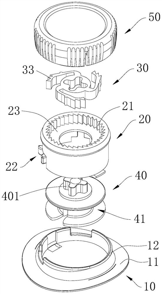
[0048] Please refer to Figure 1 to Figure 3 , In the embodiment provided by the present invention, the rotation control loose clutch includes a clutch fixed chassis 10 , a clutch body 20 , a clutch pawl 30 , a clutch output shaft 40 and a knob 50 .

[0049] Specifically, the clutch fixed chassis 10 includes a bottom plate 11 and a cylindrical portion 12 arranged on the bottom plate 11, the bottom plate 11 and the cylindrical portion 12 form a half-open space, and the diameter of the clutch main body 20 is slightly smaller than the diameter of the cylindrical portion 12, for The lower end of the clutch main body 20 is placed in the semi-open space and is stuck on the clutch fixed chassis 10 to ensure the fixed connection between the clutch main body 20 and the clutch fixed chassis 10 . The clutch fixing base 10 is arranged at the bottom of the rotating control elastic clutch, and the periphery of the base plate 11 is used for sewing on wearable objects such as shoes. Preferab...

no. 2 example

[0067] see Figure 12 and Figure 13 The difference between this embodiment and the previous embodiment is that: each unlocking portion 52 is an arc-shaped groove formed in a depression on the lower surface of the knob 50; each elastic arm 32 has a protrusion 321 correspondingly extending toward the arc-shaped groove The protrusion 321 is embedded in the arc-shaped groove and slides in the arc-shaped groove, and the arc-shaped groove radiates from a position close to the center of the knob 50 to the outer circumference, that is, between any part of the arc-shaped groove and the gear teeth 21 The distances are different, so as to guide the elastic arm 32 to deform, so that the pawl 33 and the gear teeth 21 form an engaged state or a disengaged state.

[0068] Please combine Figure 14 , in this embodiment, the lower surface of the knob 50 is provided with a driving part 51, and the driving part 51 can be a block of any shape. Since the driving part 51 is fixed on the lower su...


PUM


Abstract

A clutch capable of realizing rotary control over the degree of tightness comprises a clutch fixing chassis, a clutch body, a clutch claw piece, a clutch output shaft and a rotary knob, wherein the clutch body is fixedly installed on the clutch fixing chassis, an upper cavity and a lower cavity which communicate with each other in the up and down direction are formed in the clutch body, and gear teeth are arranged on the inner side wall of the upper cavity; the clutch claw piece is arranged in the upper cavity and comprises a claw base located in the center and a plurality of elastic arms arranged on the periphery of the claw base, and a pawl is arranged at the end, away from the claw base, of each elastic arm and faces the gear teeth; the lower end of the clutch output shaft is arranged in the lower cavity, and the upper end of the clutch output shaft is connected with the clutch claw piece into a whole, so that the clutch output shaft rotates along with the clutch claw piece; and the rotary knob rotatably covers the upper end of the clutch body, and a driving part and an unlocking part are arranged on the lower surface of the rotary knob. The degree of tightness of a rope can be rapidly adjusted through forward rotation or reverse rotation of the rotary knob, the structure is simple, and use convenience is achieved.

Description

technical field [0001] The invention relates to the technical field of daily necessities, in particular to a rotation control elastic clutch. Background technique [0002] In daily life, fixing by tether is a common fixing method used on footwear, medical protective gear or other daily necessities. Take shoes as an example. When using sports shoes or canvas shoes, the usual shoelaces are passed through the holes on the shoes, and then tied with bows or other knots. During exercise, the shoelaces are easy to loose. If you are on the road It is even more inconvenient to tighten the shoelaces when walking or carrying a lot of items. Especially in sports, once the shoelaces are loosened, accidents are easy to happen. [0003] At present, there are a few daily necessities on the market with lacing elastic devices, but their structures are complicated, and the accessories are small and numerous, resulting in complicated manufacturing processes and rapid assembly; high manufacturi...

Claims


Application Information

Patent Timeline
Patent Type & Authority Applications(China)
IPC IPC(8): F16D41/18A43C11/00
CPCF16D41/18A43C11/00
Inventor 王善炮李文栋李洪超洪朝群蔡金龙谭焜良陈少锋蔡剑明徐卫东
Owner 厦门森科艾图智能科技有限公司
Why Eureka
Try Eureka