
A device and construction method for solidifying river silt in situ

A technology of river silt and construction method, applied in chemical instruments and methods, fixed/solidified sludge treatment, electrochemical sludge treatment, etc. Ideal and other problems, to achieve the effect of uniform sludge consolidation, simple and fast construction, and weight reduction.

Active Publication Date: 2022-05-10
JIANGSU UNIV OF SCI & TECH
View PDF6 Cites 0 Cited by
  • Summary
  • Abstract
  • Description
  • Claims
  • Application Information

AI Technical Summary

Problems solved by technology

Underwater desilting usually uses mechanical equipment such as grab buckets or mud pumps to blow and stir the silt deposited on the bottom of the river to form turbid water, which flows away with the river, thereby dredging. The dredging effect of this method is not ideal , and for complex river environments such as mixed with other garbage, dredging construction is difficult and costly
Environmental dredging refers to improving water quality and avoiding secondary pollution to water as much as possible while dredging. Therefore, some special equipment is used in production to accurately control the depth and position of dredging, and clear the sludge for reprocessing. , for small rivers, this method does not have very suitable dredging construction equipment, and the cleared silt has problems such as transportation and storage, and it is necessary to prevent harmful substances in it from causing secondary pollution, and the construction process is complicated

Method used


Image

  • A device and construction method for solidifying river silt in situ
  • A device and construction method for solidifying river silt in situ
  • A device and construction method for solidifying river silt in situ

Examples


Embodiment Construction

[0038] The technical solutions of the present invention will be further described below in conjunction with the accompanying drawings and embodiments.

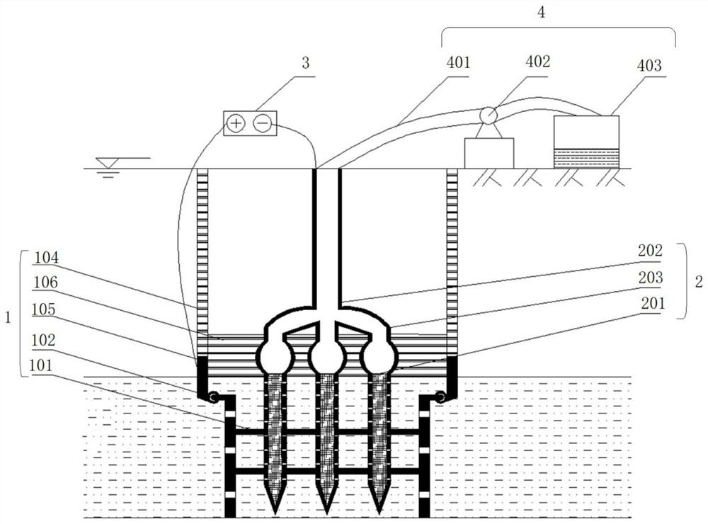
[0039] Such as figure 1 The shown in-situ solidification river silt device includes:

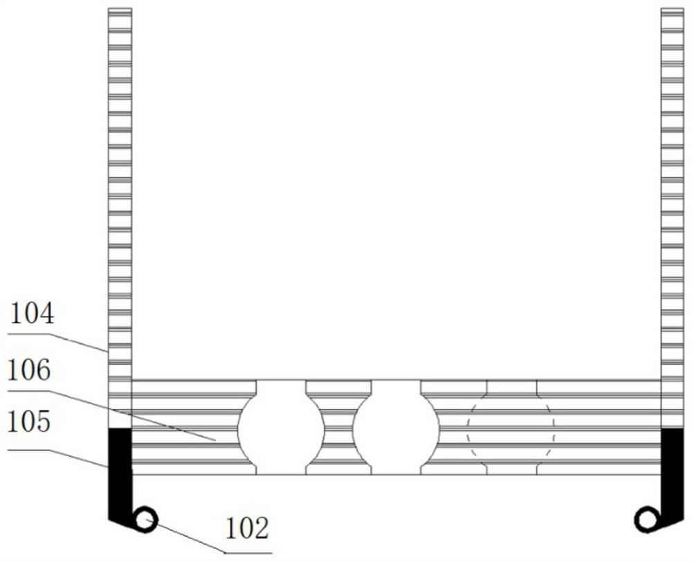
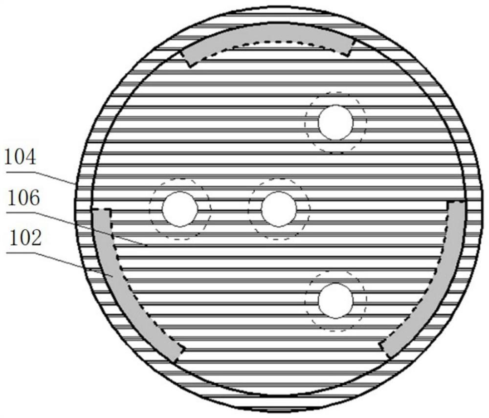
[0040] The partition conductive outer cylinder 1 is inserted from the water surface and extends into the mud, the part of the partition conductive outer cylinder 1 located in the mud is provided with a horizontally arranged conductive mesh 101, and the cylinder wall located in the mud Create multiple holes.

[0041] Conductive drainage pipe 2, the conductive drainage pipe 2 is inserted from the inside of the partition conductive outer cylinder 1 from the water surface and extends into the mud, the conductive drainage pipe 2 is inserted on the conductive mesh 101, and a plurality of hole, the conductive drainage pipe 2 is provided with mud filter cotton 201.

[0042] A DC power supply 3, the positive and negative poles of the DC power supp...


PUM


Abstract

The invention discloses an in-situ solidification device for river channel silt, comprising: a partitioned conductive outer cylinder, the partitioned conductive outer cylinder is inserted from the water surface and extends into the mud, and the part of the partitioned conductive outer cylinder located in the mud is arranged horizontally Conductive mesh, and a plurality of holes are opened on the wall of the cylinder in the mud; conductive drainage pipe, the conductive drainage pipe is inserted from the water surface of the partitioned conductive outer cylinder and extends into the mud, the conductive drainage pipe is inserted into the conductive mesh, And the cylinder wall located in the mud offers a plurality of holes, and mud filter cotton is arranged in the described conductive drainage pipe; DC power supply, the positive and negative poles of the DC power supply are respectively connected to cut off the conductive outer cylinder and the conductive drainage pipe; the pumping system, the pumping The system is connected with one end of the conductive drainage pipe protruding from the water surface; the construction method of the device is also disclosed. The device and construction method of the invention can perform in-situ solidification treatment on river channel silt, avoiding problems such as transportation and storage in the process of cleaning silt, and are more environmentally friendly.

Description

technical field [0001] The invention relates to the technical field of geotechnical engineering, in particular to an in-situ solidifying river channel silt device and a construction method. Background technique [0002] With the development of modern urban industry, a large amount of construction waste, domestic waste and industrial waste water are discharged into the river, especially in the siltation of small and medium rivers, which weakens the ability of the river to regulate and store floods and prevent and reduce disasters to a certain extent. It will affect the unobstructed water flow of the river and the normal navigation of ships, so it is necessary to carry out dredging treatment on the river. [0003] Existing river channel dredging methods mainly include drain dredging, underwater dredging and environmental dredging. Drainage and dredging refers to the construction of temporary cofferdams in the construction section of small rivers without flood control, drainag...

Claims


Application Information

Patent Timeline
Patent Type & Authority Patents(China)
IPC IPC(8): E02D3/11C02F11/00C02F11/15
CPCE02D3/11C02F11/006C02F11/008C02F11/15
Inventor 张雷潘卓杰王炳辉姜朋明王丽艳刘义张文博栾佶金海晖许荣泽
Owner JIANGSU UNIV OF SCI & TECH
Learn More