
Flexible direct current charging system dynamically distributed along with transformer capacity

A dynamic distribution, flexible DC technology, applied in electric vehicle charging technology, charging station, system integration technology, etc., can solve the problems of system impact, system security reduction, increase of fault points, etc., to achieve simple maintenance process and reduce maintenance. Maintenance cost, simple effect of control process

Pending Publication Date: 2021-10-22
山东明大电器股份有限公司
View PDF5 Cites 0 Cited by
  • Summary
  • Abstract
  • Description
  • Claims
  • Application Information

AI Technical Summary

Problems solved by technology

[0007] 2. The existence of a large number of switching devices reduces the security of the system
If any DC contactor sticks, there is a risk of DC output short circuit
[0008] 3. Due to the complexity of the entire charging pile, the material cost and manufacturing cost are relatively high
Complex hardware leads to more failure points, and maintenance is more troublesome
[0009] 4. Power distribution is based on a single module. The power of a single module determines the magnitude of power distribution, and complete flexible charging cannot be achieved.
With the development and innovation of technology, the power of a single module is getting bigger and bigger. The mainstream of the market has changed from 15kW and 20kW power modules to the current 30kW power module. The simple switching contactor has lost the role of flexible charging.
[0010] In addition, as a high-power power conversion device, the charging module has a high failure rate after being used for a long time in an environment with a low outdoor protection level
Based on the power distribution module with the charging module as the core, the failure of a single charging module will have a significant impact on the entire system

Method used


Image

  • Flexible direct current charging system dynamically distributed along with transformer capacity

Examples


Embodiment Construction

[0027] The following will clearly and completely describe the technical solutions in the embodiments of the present invention with reference to the accompanying drawings in the embodiments of the present invention. Obviously, the described embodiments are only some, not all, embodiments of the present invention. Based on the embodiments of the present invention, all other embodiments obtained by persons of ordinary skill in the art without making creative efforts belong to the protection scope of the present invention.

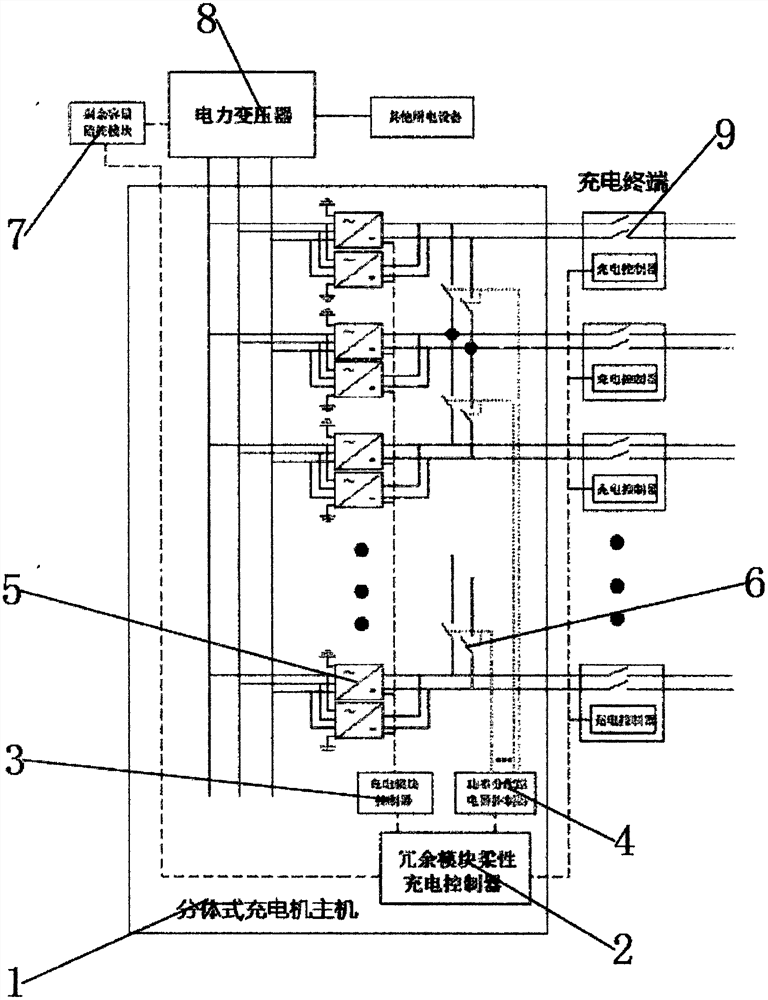
[0028] see figure 1 , in an embodiment of the present invention, a flexible DC charging system dynamically allocated according to the capacity of the transformer, including a split-type charging pile host 1, a remaining capacity monitoring module 7, a charging module 5, and a charging terminal 9. The split-type charging pile host 1 is composed of power The conversion main circuit and the control system are composed. The power conversion main circuit is powered...


PUM


Abstract

The invention discloses a flexible direct current charging system dynamically distributed along with transformer capacity in the field of direct current charging, which comprises a split type charging pile host, a residual capacity monitoring module, a charging module and a charging terminal, and is characterized in that the split type charging pile host is composed of a power conversion main loop and a control system. The residual capacity monitoring module is used for recording the operation state of the transformer, data is transmitted to the background system through 4G network transmission, the background system can predict the use capacity change state of the transformer through big data analysis, more reasonable resource allocation can be carried out, the effective high power capacity and the utilization rate of power equipment are improved. Through reasonable configuration, the charging requirement of a user is met to the greatest extent, the control process is simple, the number of switching devices is small, the maintenance process is simple, the residual capacity of the transformer and the voltage and current power of real-time operation of the transformer are detected in real time, and the system safety level is high.

Description

technical field [0001] The invention relates to the field of direct current charging, in particular to a flexible direct current charging system dynamically allocated according to the capacity of a transformer. Background technique [0002] With the rapid development of new energy vehicles, the demand for charging piles is increasing. Traditional charging piles are divided into DC charging piles and AC charging piles. DC charging piles have a large output power and can quickly charge electric vehicles. Most of the public parking lots are built with DC charging piles. [0003] DC charging piles are further divided into integrated DC charging piles and split DC charging piles. The integrated DC charging pile has a simple structure and is suitable for mass production, but the power utilization rate of the charging pile is relatively low during the use of the charging station. The split-type charging pile main unit is separated from the charging gun terminal. According to the ...

Claims


Application Information

Patent Timeline
Patent Type & Authority Applications(China)
IPC IPC(8): B60L53/31B60L53/62B60L53/16H02J7/04H02J13/00
CPCB60L53/31B60L53/62B60L53/16H02J7/04H02J13/00001H02J13/00002H02J13/00016Y04S10/50Y04S30/12Y02T10/70Y02T10/72Y02T10/7072Y02T90/12Y02T90/14Y02T90/167Y02E40/70
Inventor 王险峰王保伦
Owner 山东明大电器股份有限公司
Learn More