
Injection molding apparatus and injection molding method

An injection molding and equipment technology, applied in the field of injection molding equipment and injection molding, can solve the problems of no mold exhaust design, uneven gas pressure distribution, difficult gas control, etc., to achieve good mold exhaust design, avoid gas Effects of uneven pressure distribution, good quality and yield

Pending Publication Date: 2021-10-22
CHUNG YUAN CHRISTIAN UNIVERSITY
View PDF5 Cites 0 Cited by
  • Summary
  • Abstract
  • Description
  • Claims
  • Application Information

AI Technical Summary

Problems solved by technology

However, the disadvantage of the above method is that the traditional gas needle design is not easy to control the gas, which may cause uneven distribution of gas pressure, and even cause gas penetration due to excessive gas pressure, which will damage the appearance of the product.
Furthermore, the above approach does not provide a good mold venting design

Method used


Image

  • Injection molding apparatus and injection molding method
  • Injection molding apparatus and injection molding method
  • Injection molding apparatus and injection molding method

Examples


Embodiment Construction

[0020] Reference will now be made in detail to the exemplary embodiments of the present invention, examples of which are illustrated in the accompanying drawings. Wherever possible, the same reference numbers are used in the drawings and descriptions to refer to the same or like parts.

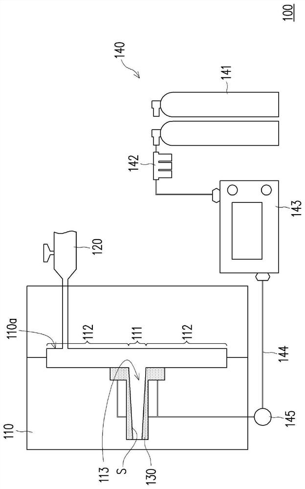
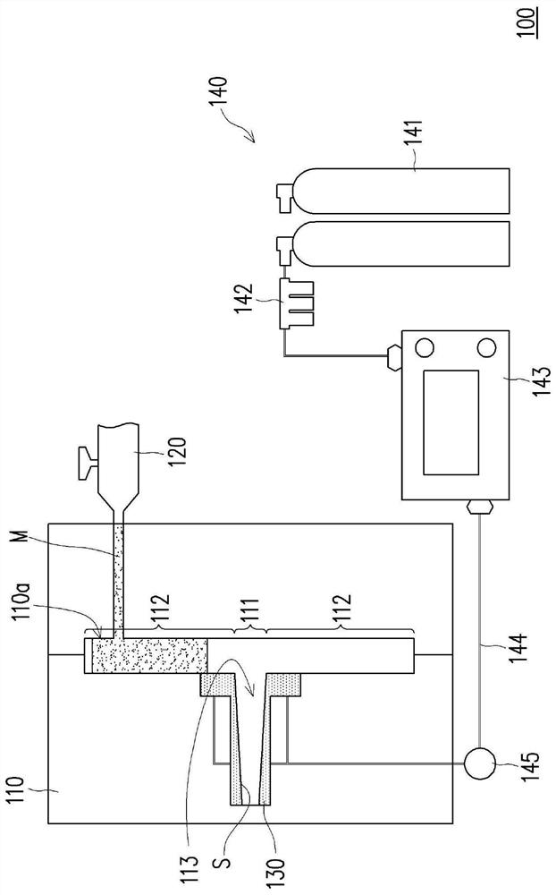
[0021] figure 1 It is a schematic diagram of an injection molding device according to an embodiment of the present invention. Please refer to figure 1 , the injection molding equipment 100 includes a mold 110 , an injection device 120 , a porous structure 130 and a gas driving unit 140 . The mold 110 has a mold cavity 110a. The injection device 120 is suitable for injecting the material M ( Figure 3A ) to the mold cavity 110a so that the material M ( Figure 3A ) is shaped into a molded object 50 ( Figure 3B ).

[0022] The porous structure 130 is disposed on the inner surface S of the mold cavity 110a. The gas driving unit 140 is connected to the mold 110 and is suitable for driving...


PUM


Abstract

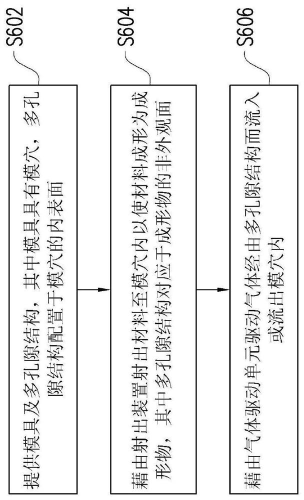
An injection molding apparatus includes a mold, an injection device, a porous structure, and a gas-driven unit. The mold has a mold cavity. The injection device is adapted to inject a material into the mold cavity so that the material is formed into a forming article. The porous structure is disposed on an inner surface of the mold cavity and corresponds to a non-appearance surface of the forming article. The gas-driven unit is connected to the mold and is adapted to drive a gas to flow into or flow out of the mold cavity through the porous structure. In addition, an injection molding method is also provided. The injection molding apparatus and the injection molding method of the present invention can make the gas pressure distribution in the mold cavity uniform, and have a good mold exhaust effect.

Description

technical field [0001] The present invention relates to a molding equipment and a molding method, and in particular to an injection molding equipment and an injection molding method. Background technique [0002] During the molding process of injection molded products, the material may shrink due to thermal expansion and contraction, causing defects in the molded product, which in turn leads to dents on the appearance of the product. Generally speaking, the thicker the area of ​​the product is, the more the material shrinks, and the more prone to defects. [0003] Traditionally, external gas-assisted molding is mostly used, and an air needle is installed near the thicker area of ​​the product. After injection molding, the gas is fed through the air needle, so that the gas enters the mold cavity through the air needle, so as to push the molten material in the mold cavity to the appearance mold surface. However, the disadvantage of the above method is that the traditional ga...

Claims


Application Information

Patent Timeline
Patent Type & Authority Applications(China)
IPC IPC(8): B29C45/03B29C45/34
CPCB29C45/03B29C45/34B29C33/3814B29C2045/1702B29C45/1701B29C45/1703B29C45/1704B29C45/37B29C45/57
Inventor 陈夏宗张咏翔张哲维蔡碧霖
Owner CHUNG YUAN CHRISTIAN UNIVERSITY
Learn More