Prefabricated concrete wall type auxiliary supporting assembly
A prefabricated concrete and auxiliary support technology, which is used in construction, building structure, and building material processing, etc., can solve the problems of single structure, unstable support, lack of wind resistance, etc., and achieve the effect of precise adjustment
- Summary
- Abstract
- Description
- Claims
- Application Information
AI Technical Summary
Problems solved by technology
Method used
Image
Examples
Embodiment 1
[0027] The following will clearly and completely describe the technical solutions in the embodiments of the present invention with reference to the accompanying drawings in the embodiments of the present invention. Obviously, the described embodiments are only some, not all, embodiments of the present invention. Based on the embodiments of the present invention, all other embodiments obtained by persons of ordinary skill in the art without making creative efforts belong to the protection scope of the present invention.
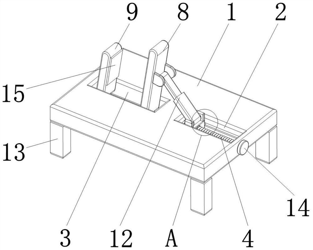
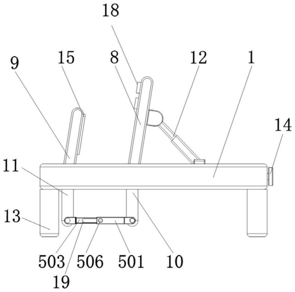
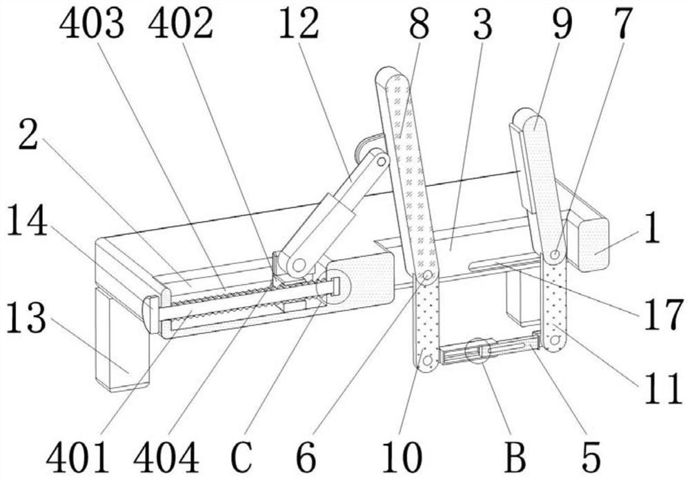
[0028] Such as Figure 1 to Figure 6 As shown, the present invention provides a prefabricated concrete wall-type auxiliary support assembly, including a fixing seat 1, a first chute 2 is provided on the right side of the top of the fixing seat 1, and notches are provided on the left side of the top and bottom of the fixing seat 1 3. The inside of the first chute 2 is fixedly connected with a support member 4 , the bottom of the notch 3 is movably installed wit...
Embodiment 2
[0040] The inventor found in practice that the prefabricated concrete wall-type auxiliary support assembly provided in Example 1 has the following problems in use: 1. The support assembly may be subjected to external forces such as wind blowing and vibration; 2. There are wall panels The two faces clamped by the support assembly are non-parallel cases. In view of the above problems, the second embodiment of the present invention improves the first embodiment, the technical solution of the second embodiment includes all the technical solutions of the first embodiment, and the implementation of the second embodiment is different from the single implementation of the first embodiment. will have an impact.
Embodiment 2
[0043] In Example 2, when the two surfaces of the wall board held by the support assembly are non-parallel, the support board 8 is attached to the wall board and rotates to drive the first connecting rod 10 to rotate around the fixed shaft 6 to drive the rectangular tube 501 to rotate. The movement further drives the rectangular rod 503 to move, and the rectangular rod 503 drives the second connecting rod 11 to rotate around the movable shaft 7, so that the fixed plate 9 can adapt to the inclination angle of the wall surface, and at the same time, the movable shaft 7 is in the second position by moving the fixed plate 9. Sliding in the chute 17, the movable shaft 7 drives the second connecting rod 11 and then drives the rectangular rod 503 to move to a suitable position in the cavity 502 so that the fixing plate 9 can fit the wallboard, and then the rectangular tube 501 and the The rectangular rod 503 is locked, so that the supporting plate 8, the fixing plate 9, and the fixing...
PUM
 Abstract
Description
Claims
Application Information
 - R&D Engineer
- R&D Manager
- IP Professional
- Industry Leading Data Capabilities
- Powerful AI technology
- Patent DNA Extraction
Browse by: Latest US Patents, China's latest patents, Technical Efficacy Thesaurus, Application Domain, Technology Topic, Popular Technical Reports.
© 2024 PatSnap. All rights reserved.Legal|Privacy policy|Modern Slavery Act Transparency Statement|Sitemap|About US| Contact US: help@patsnap.com


