Chain power traction device and material conveying line

A technology of power traction and conveying line, which is applied in the direction of conveyor, transportation and packaging, can solve the problems of insufficient machining accuracy and assembly accuracy, insufficient transmission accuracy of material conveying line, etc.

Pending Publication Date: 2021-10-15
TIANJIN DAYIN BUILDING MATERIAL CO LTD
View PDF0 Cites 0 Cited by
  • Summary
  • Abstract
  • Description
  • Claims
  • Application Information

AI Technical Summary

Problems solved by technology

[0004] The present invention aims to provide a chain power traction device and a material conveying line to solve the problem of insufficient transmission accuracy of the material conveying line in the prior art due to insufficient processing accuracy and assembly accuracy among its components

Method used


Image

  • Chain power traction device and material conveying line
  • Chain power traction device and material conveying line
  • Chain power traction device and material conveying line

Examples


Embodiment 1

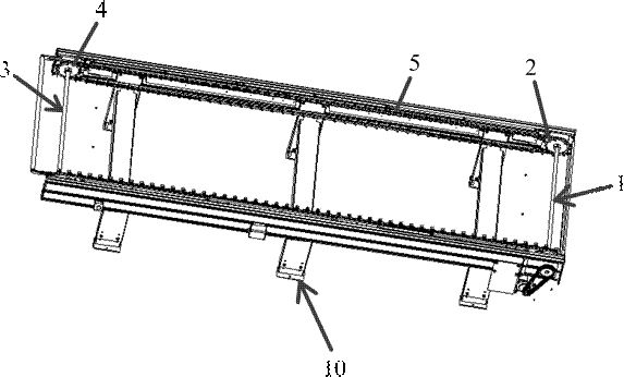
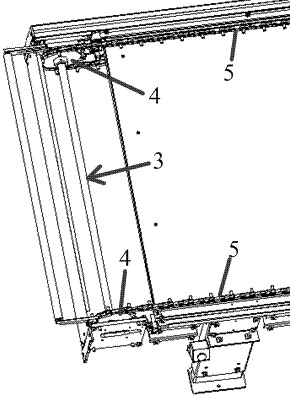
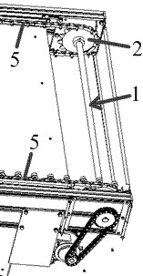
[0053] A chain powered traction device is described, such as Figure 1 to Figure 3 shown, which includes:

[0054] The driving transmission shaft 1, the driving transmission shaft 1 is driven to rotate, and at least two driving transmission wheels 2 are arranged on its length direction, and the driving transmission wheels 2 are fixedly connected with the driving transmission shaft 1; In the embodiment, the two ends of the driving transmission shaft 1 are respectively provided with two driving transmission wheels 2, and the two driving transmission wheels 2 are connected to the two driven transmission wheels through the two transmission chains 5 respectively. 4 transmission connected;

[0055] The driven rotating shaft 3, the driven driving wheel 4 corresponding to the position of the driving driving wheel 2 is provided on the length direction of the driven rotating shaft 3, and the driven driving wheel 4 is connected to the said driven driving wheel 4 through a transmission c...

Embodiment 2

[0065] A material conveying line is documented, such as Figure 8 and Figure 6 shown, including:

[0066] chain powered traction devices; and,

[0067] A frame 10, on which the chain power traction device is arranged. In this embodiment, the driving mechanism 9 is a driving motor installed on the frame 10, and the driving motor is connected to the driving wheel 12 at the end of the driving transmission shaft 1 through a driving chain 11;

[0068] Conveying roller 13, described conveying roller 13 is a plurality of and is arranged on described transmission chain 5, is used for conveying material; The transmission chain 5 is connected in cooperation with the plug-in rotation; Figure 7 As shown, the transmission chain 5 includes: a connecting pin 16 for connecting adjacent chain plates 15; The rotation gap in which the conveying roller 13 rotates. The above-mentioned plug-in column 14 is connected with the transmission chain 5 in cooperation with insertion and rotation, s...


PUM


Abstract

The invention relates to a chain power traction device and a material conveying line. The chain power traction device comprises a driving transmission shaft and a driven rotating shaft; the driving transmission shaft is driven to rotate, at least two driving transmission wheels are arranged in the length direction of the driving transmission shaft, and the driving transmission wheels are fixedly connected with the driving transmission shaft; driven transmission wheels corresponding to the driving transmission wheels in position are arranged in the length direction of the driven rotating shaft, and the driven transmission wheels are in transmission connection with the driving transmission wheels through transmission chains; at least one of the at least two driven transmission wheels is a position compensation transmission wheel rotationally connected with the driven rotating shaft; and the driven transmission wheel except the position compensation transmission wheel is fixedly connected with the driven rotating shaft. By means of the structure, the problem that in the prior art, due to the fact that machining precision and assembling precision of all parts of a material conveying line are insufficient, transmission precision of the material conveying line is insufficient can be solved.

Description

technical field [0001] The invention relates to the technical field of a chain power traction device, in particular to a chain power traction device and a material conveying line. Background technique [0002] Chain power traction devices are widely used in product transportation in production lines. The chain power traction device includes a driving transmission shaft and a driven rotating shaft. The driving drive shaft drives the driven rotating shaft to rotate through the transmission chain, so as to realize the circular rotation of the transmission chain around the circumferential direction, and then drives the products on the material conveying line to move to the next station through the transmission roller and other components on the transmission chain. [0003] In the chain power traction device in the prior art, the two ends of the driving transmission shaft and the driven transmission shaft are respectively provided with transmission wheels fixedly connected with ...

Claims


Application Information

Patent Timeline
IPC IPC(8): B65G23/06B65G23/04B65G17/06B65G17/34
CPCB65G23/06B65G23/04B65G17/064B65G17/34
Inventor 闫俊杰梅能敏王龙涛雷剑平贾楠森宋艳宾曹国栋
Owner TIANJIN DAYIN BUILDING MATERIAL CO LTD
Why Eureka
Try Eureka