Infrared induction control circuitry and liquid discharge device

A technology of infrared induction and control circuit, applied in the field of infrared induction, can solve the problems of high cost, complicated anti-interference circuit design and software design, etc., to reduce the circuit cost, solve the complex software design, and improve the detection accuracy.

Pending Publication Date: 2021-10-12
佛山普瑞威尔科技有限公司
View PDF8 Cites 0 Cited by
  • Summary
  • Abstract
  • Description
  • Claims
  • Application Information

AI Technical Summary

Problems solved by technology

[0003] In this embodiment, an infrared induction control circuit and a liquid outlet device are provided to solve the problems of complex anti-interference circuit design and software design and high cost in the related art

Method used


Image

  • Infrared induction control circuitry and liquid discharge device
  • Infrared induction control circuitry and liquid discharge device
  • Infrared induction control circuitry and liquid discharge device

Examples


Embodiment Construction

[0037] In order to make the purpose, technical solutions and advantages of the present application, the present application will be described and illustrated below with reference to the accompanying drawings and examples.

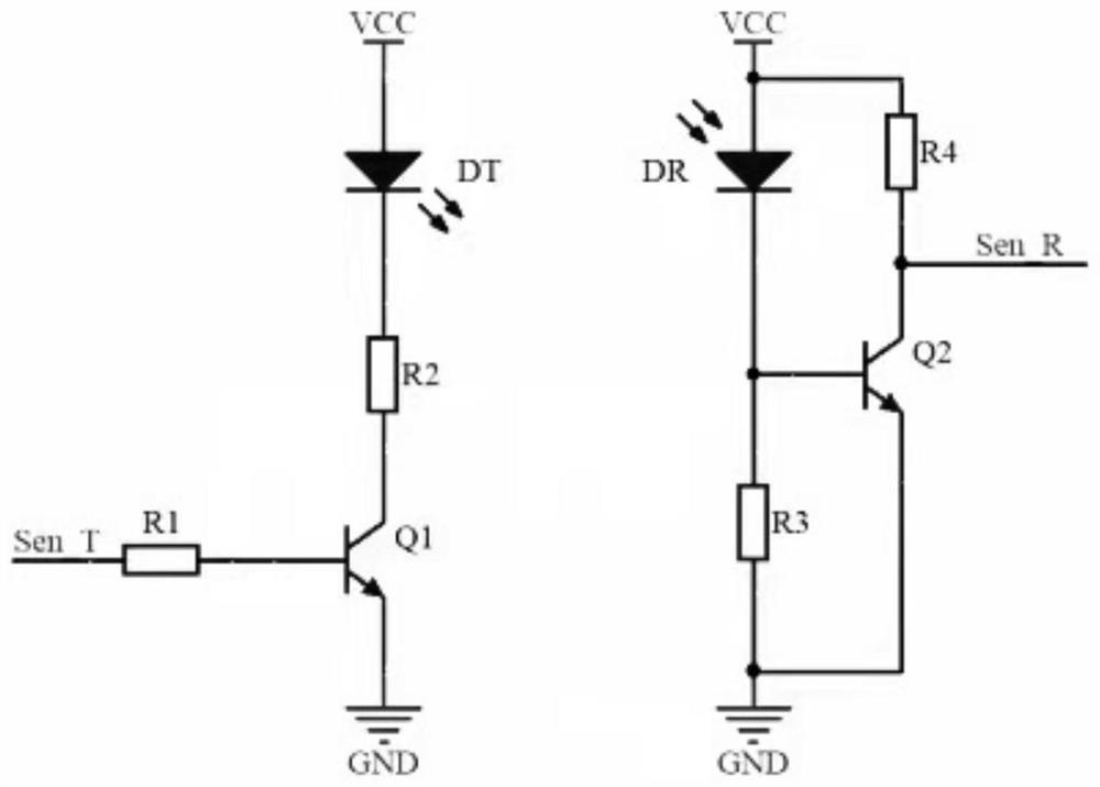
[0038] This embodiment provides an infrared sensing control circuit. figure 1 It is a circuit schematic of an infrared induction control circuit according to this application. figure 1 As shown, the circuit includes an infrared transmit circuit, an infrared detecting circuit, and a central processor. The infrared transmit circuit includes a first resistor R1, a second resistance R2, a first trichotherap, a first trichothe, and an infrared transmit tube DT. Infrared detection circuit, including the third resistance R3, the fourth resistor R4, the second three-pole Q2, and the infrared receiving tube DR. The central processor is connected to the collector of the first resistor R1 and the second three pole Q2. Among them, the central processor controls the conduct...


PUM


Abstract

The invention relates to infrared induction control circuitry and a liquid discharge device. The circuitry is characterized in that the circuitry comprises an infrared emission circuit which comprises a first resistor, a second resistor, a first triode and an infrared emission tube; an infrared detection circuit comprising a third resistor, a fourth resistor, a second triode and an infrared receiving tube; a central processing unit connected with the first resistor and the collector electrode of the second triode; wherein the central processing unit inputs a control signal to the infrared emission circuit to control the on and off of the infrared emission tube, and the central processing unit transmits the control signal to the infrared detection circuit after the infrared detection circuit receives an infrared signal emitted by the infrared emission tube. Whether a detection signal is detected in the infrared detection circuit is judged according to the infrared signal, and if yes, it is judged that a detected object is in an induction area; the detection signal is a pulse signal which is consistent with the pulse interval of the control signal. According to the invention, the problems of complex infrared induction anti-interference circuit design and software design, high cost and the like are solved.

Description

Technical field [0001] The present application relates to the field of infrared inductance, and in particular, there is an infrared induction control circuit, a liquid discharge device. Background technique [0002] Infrared induction techniques are infrared reflection principles, and the infrared rays emitted by infrared emission tubes are transmitted to the control elements (such as relays, motors, solenoid valves) by microcompression within the integrated line due to the detected object blocking to the infrared receiving tube. Reach the purpose of automatic control. For example, when the infrared sensing element in the induction handle liquid detects that the hand of the human body stays in the induction zone, the integrated circuit is transmitted to the electronic water pump. The current circuit and device currently passed through the infrared reflection principle, the receiving tube is difficult to distinguish the source of the receiving light during direct shooting or refle...

Claims


Application Information

Patent Timeline
Patent Type & Authority Applications(China)
IPC IPC(8): H03K17/945
CPCH03K17/945
Inventor 周露露
Owner 佛山普瑞威尔科技有限公司
Why Eureka
Try Eureka