Electric shifting lifter

A lift and lift mechanism technology, applied in medical science, hospital beds, hospital equipment, etc., can solve the problems of insufficiency, easy damage, exposed electric push rods, etc.

Pending Publication Date: 2021-10-12
泰州洛克机电制造有限公司
View PDF2 Cites 0 Cited by
  • Summary
  • Abstract
  • Description
  • Claims
  • Application Information

AI Technical Summary

Problems solved by technology

The electric shifter in the prior art has the following disadvantages: 1. The main structure is generally made of steel, which increases its own weight and processing cost, and the processing technology is complicated; 2. The electric push rod is exposed, which reduces safety and is easy to damage; 3. 2. Some lifting machines have a single posture when lifting the patient, and the patient is uncomfortable to lift
[0004] An electric lift with application number 201822216857.3, the patent is aimed at lifting patients, which is inconvenient for patients to operate in daily life, and can not meet some daily needs; application number 201811219873.6 has an auxiliary lift The wheelchair with the functions of sitting and toileting can meet some daily needs, but it is inconvenient to sit up and lie down, and can only sit and stand in one direction, which is not conducive to the patient's physical training and blood circulation

Method used


Image

  • Electric shifting lifter
  • Electric shifting lifter
  • Electric shifting lifter

Examples


Embodiment Construction

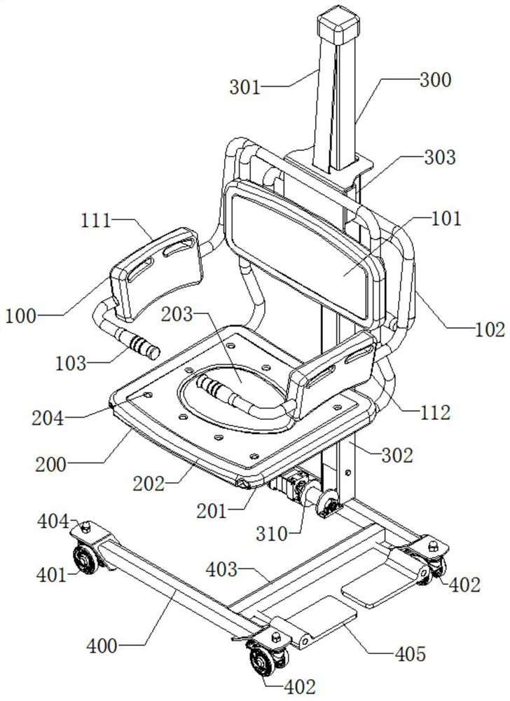
[0019] In order to make the object, technical solution and advantages of the present invention clearer, the following in conjunction with the attached figure 1 , attached figure 2 , attached image 3 , Figure 4 , Figure 5 and Figure 6 And working principle, the present invention is described in further detail.

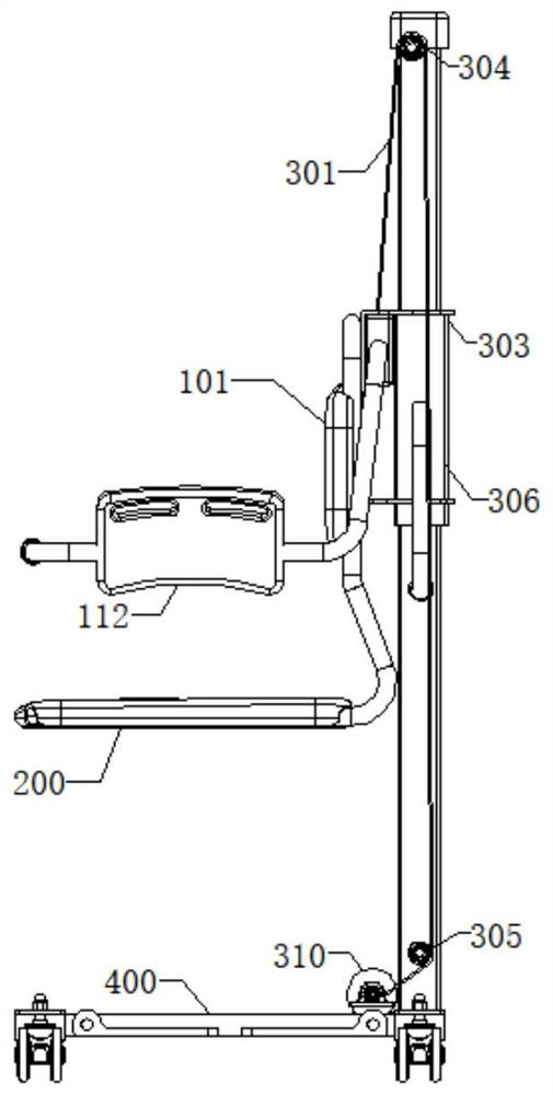
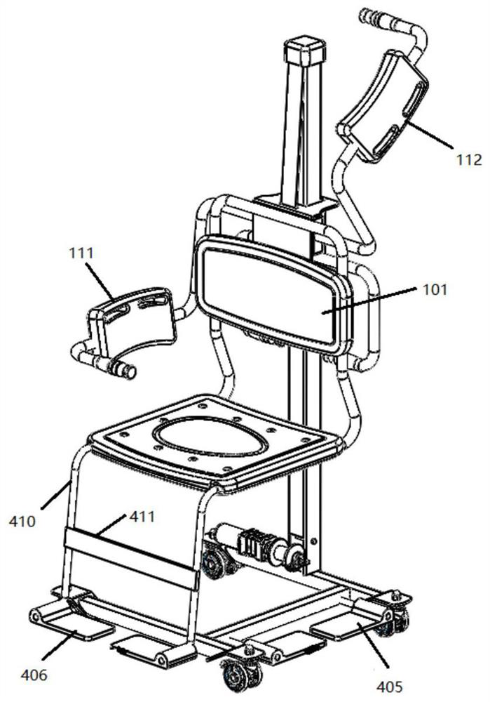
[0020] refer to figure 1 , the electric displacement lifter is composed of a handle mechanism 100, a seat plate 200, a lifting mechanism 300 and a chassis mechanism 400, the lower end of the lifting mechanism 300 is fixed on the chassis mechanism 400, and the upper end of the lifting mechanism 300 is provided with a lifting slide Block 301, the handle mechanism 100 is installed on the lifting slider 301 of the lifting mechanism 300 through the fixed backrest 101, there is a fixed backrest 101 in the middle of the handle mechanism 100, and the left and right sides of the fixed backrest 101 are the left flip backrest 111 and the right flip backrest 112, the pat...


PUM


Abstract

The invention discloses an electric shifting lifter. The lifter comprises a gripper mechanism, a seat plate, a lifting mechanism and a bottom frame mechanism; the lower end of the lifting mechanism is fixed to the bottom frame mechanism; a lifting sliding block is arranged at the upper end of the lifting mechanism; the gripper mechanism is installed on the lifting sliding block of the lifting mechanism through a fixed backrest; the fixed backrest is arranged in the middle of the gripper mechanism; a left turnover backrest and a right turnover backrest are arranged on the left side and the right side of the fixed backrest; a patient can sit in three directions through the fixed backrest, the left turnover backrest and the right turnover backrest; one end of the left turnover backrest and one end of the right turnover backrest are connected with the lifting sliding block at the rear end of the fixed backrest through movable handrails; the other ends of the left turnover backrest and the right turnover backrest are provided with fixed handrails; the movable handrail at the upper end of the fixed backrest is connected with a traction belt; one end of the traction belt is connected with the movable handrail of a seat; and the other end of the traction belt penetrates through the interior of a stand column to be connected with a hoisting mechanism. The traction belt is wound and released to drive the seat plate to ascend and descend by controlling forward and reverse rotation of a motor of the hoisting mechanism.

Description

technical field [0001] The invention relates to the field of vehicle medical equipment, in particular to an electric displacement lift. Background technique [0002] In the age of aging, many people with paraplegia, hemiplegia, fractures, inconvenient legs and feet or long-term bedridden must rely on caregivers for daily care. Long-term care of bedridden patients is exhausting and heavy work. In order to improve the care ability of bedridden patients, solve the inconvenience of patients getting out of bed to go to the toilet and bathe, and reduce the labor burden of caregivers, there is an urgent need for convenient and labor-saving movement, such as electric displacement machines. The electric lift can realize the safe transfer of paralyzed, injured patients or the elderly between beds, seats, etc., and solve the movement of the elderly, disabled, bedridden patients and other inconvenient people and the positioning control of the patient's position, reducing the Reduce the...

Claims


Application Information

Patent Timeline
Patent Type & Authority Applications(China)
IPC IPC(8): A61G5/00A61G5/10A61G7/10A61G7/14A61G5/12
CPCA61G5/00A61G5/10A61G5/1051A61G5/1056A61G5/1059A61G5/122A61G7/1001A61G7/1013A61G7/1025A61G7/1046A61G7/1073A61G7/1015A61G5/1005A61G5/1037A61G5/1091A61G5/1045
Inventor 樊荣朱勇
Owner 泰州洛克机电制造有限公司
Why Eureka
Try Eureka