
Display panel, preparation method and display device

A display panel and display area technology, which is applied in semiconductor/solid-state device manufacturing, diodes, semiconductor devices, etc., can solve the problems of visual differences in the camera placement area, affect the display effect of the display panel, and reduce the local brightness of the display panel. difference, improving the effect of poor light transmittance and high light transmittance

Pending Publication Date: 2021-10-01
BOE TECH GRP CO LTD +1
View PDF0 Cites 0 Cited by
  • Summary
  • Abstract
  • Description
  • Claims
  • Application Information

AI Technical Summary

Problems solved by technology

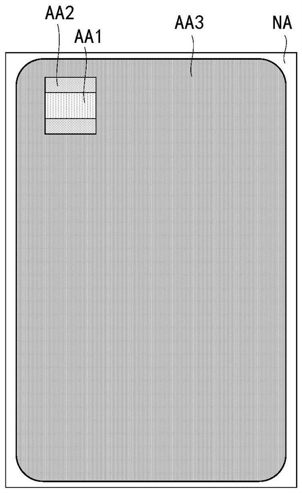
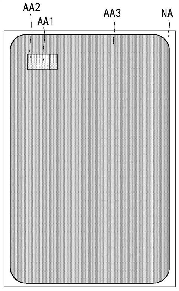
[0004] The embodiment of the present application provides a display panel, a preparation method, and a display device, which can solve the problem of local brightness reduction caused by the local PPI reduction of the existing display panel, causing visual differences between the camera placement area and the normal display area, and affecting the display effect of the display panel. The problem

Method used


Image

  • Display panel, preparation method and display device
  • Display panel, preparation method and display device
  • Display panel, preparation method and display device

Examples


Embodiment Construction

[0064] In order to better understand the technical solutions provided by the embodiments of this specification, the technical solutions of the embodiments of this specification will be described in detail below through the drawings and specific examples. The detailed description of the technical solutions of the embodiments is not a limitation to the technical solutions of this specification. In the case of no conflict, the embodiments of this specification and the technical features in the embodiments can be combined with each other.

[0065] In this document, relational terms such as first and second etc. are used only to distinguish one entity or operation from another without necessarily requiring or implying any such relationship between these entities or operations. Actual relationship or sequence. Furthermore, the term "comprises", "comprises" or any other variation thereof is intended to cover a non-exclusive inclusion such that a process, method, article, or apparatus...


PUM


Abstract

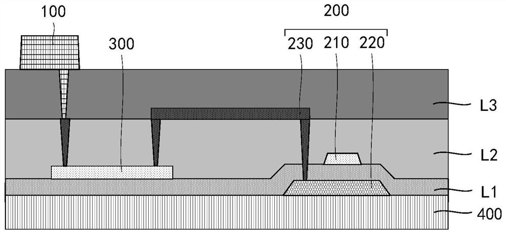
The invention discloses a display panel, a preparation method and a display device, relates to the technical field of display, and can solve the problem that the display effect of the display panel is affected by visual difference between a camera placement area and a normal display area due to local brightness reduction caused by local PPI reduction of an existing display panel. The display panel includes a light emitting device, a driving device including a gate electrode, and a first connecting wire, wherein the driving device is electrically connected with the light-emitting device through the first connecting wire, and the first connecting wire and the gate electrode are prepared through the same transparent conductive layer.

Description

technical field [0001] The present application relates to the field of display technology, in particular to a display panel, a manufacturing method and a display device. Background technique [0002] In recent years, in order to maximize the screen-to-body ratio of mobile display products, technologies such as notch screens, water drop screens, and digging holes in the screen have emerged. This type of technology reduces the screen-to-body ratio problem caused by the camera occupying the frame by partially digging a hole in the display area and placing a camera in the hole. However, the above technology still needs to dig out part of the display area to form a special-shaped display area, and it is difficult to realize a full screen. [0003] In order to avoid sacrificing the display area, the technology of placing a camera under the screen has emerged, which can replace local digging in the display area, and reduce the local PPI (Pixels Per Inch, the number of pixels per i...

Claims


Application Information

Patent Timeline
Patent Type & Authority Applications(China)
IPC IPC(8): H01L27/12H01L21/77H01L27/32
CPCH01L27/124H01L27/1259H10K59/65
Inventor 袁长龙孙阔曹席磊
Owner BOE TECH GRP CO LTD
Learn More