Single-tube telescope and shading tube thereof
A telescope and monocular technology, which is applied in the field of telescopes, can solve problems such as being easily affected by the external environment, easily generating fog, and affecting the observation quality of monocular telescopes, so as to achieve the effect of improving the observation quality
- Summary
- Abstract
- Description
- Claims
- Application Information
AI Technical Summary
Problems solved by technology
Method used
Image
Examples
Embodiment 1
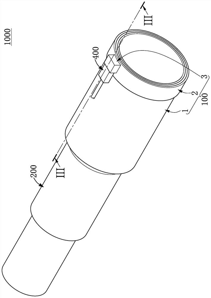
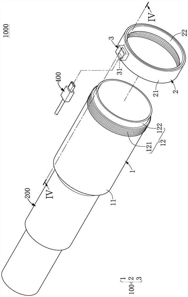
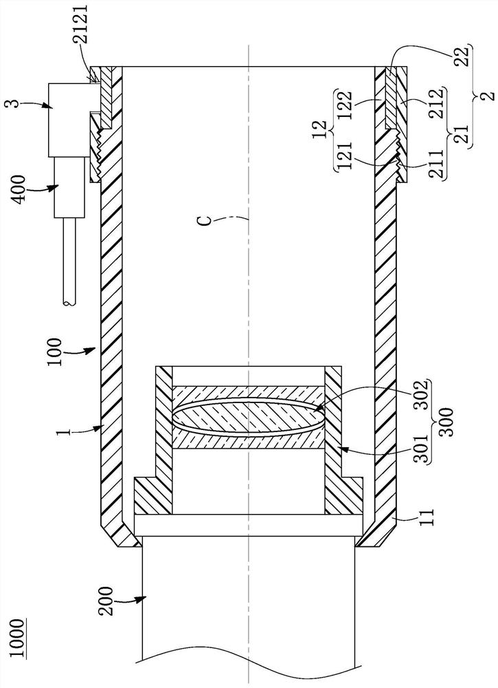
[0026] see Figure 1 to Figure 4 As shown, it is Embodiment 1 of the present invention. This embodiment discloses a monocular telescope 1000, which includes a lens barrel 200, an optical mirror base 300 fixed on the lens barrel 200, and a shading tube 100 movably sleeved on the lens barrel 200 . Wherein, although the light-shielding tube 100 of this embodiment is described as collaborating with the lens barrel 200 and the optical mirror base 300, in other embodiments of the present invention not shown, the light-shielding tube 100 can also be used in The relevant structures of other telescopes are not limited to those contained in this embodiment.
[0027] The lens barrel 200 contains at least one optical lens (not shown in the figure), and the light-shielding barrel 100 is a hollow tube with no optical lens fixed on its inner edge, and the optical mirror base 300 is It is located in the light shielding tube 100 and fixed on the end of the lens barrel 200 . Wherein, the op...
Embodiment 2
[0039] see Figure 5 As shown, it is the second embodiment of the present invention. This embodiment is similar to the first embodiment above, so the same parts of the two embodiments (such as: the metal cylinder 1, the heating ring 2, the electrical connector 3, the The lens barrel 200, the optical lens mount 300, and the power cord 400) will not be described in detail, and the differences between this embodiment and the first embodiment are roughly described as follows:
[0040] In this embodiment, the light-shielding cylinder 100 further includes a focus sheet 500, and the focus sheet 500 is (detachably) disposed at one end of the carrying ring 21 away from the first end 11 , so as to facilitate the focusing operation of the monocular telescope 1000. Wherein, the specific structure of the focus sheet 500 can be adjusted and changed according to design requirements, and the present invention is not limited here.
Embodiment 3
[0042] see Image 6 As shown, it is the third embodiment of the present invention. This embodiment is similar to the above-mentioned first embodiment, so the similarities between the two embodiments (such as: the lens barrel 200, the optical mirror holder 300, and the power cord 400) are then No more details, but the differences between this embodiment and Embodiment 1 are roughly described as follows:
[0043] In this embodiment, the heating ring 2 is further defined as an electric heating wire 22 (that is, the heating ring 2 does not include the bearing ring body 21), and the heating ring 2 is fixed on the metal cylinder 1 on the inner surface of the second end portion 12, and the electrical connector 3 is disposed on the outer surface of the metal cylinder 1. Wherein, the space in the metal cylinder 1 is defined with a light travel area corresponding to the plurality of lenses 302 of the optical mirror base 300 and a dark area outside the light travel area, and the above-m...
PUM
 Abstract
Description
Claims
Application Information
 - R&D Engineer
- R&D Manager
- IP Professional
- Industry Leading Data Capabilities
- Powerful AI technology
- Patent DNA Extraction
Browse by: Latest US Patents, China's latest patents, Technical Efficacy Thesaurus, Application Domain, Technology Topic, Popular Technical Reports.
© 2024 PatSnap. All rights reserved.Legal|Privacy policy|Modern Slavery Act Transparency Statement|Sitemap|About US| Contact US: help@patsnap.com


