
Joint unit module and leg robot

A robot and module technology, which is applied in motor vehicles, transportation and packaging, etc., can solve the problems of low center of mass of the robot and large torque required by the steering gear, and achieve the effect of centralized structure, small installation space, and improved center of mass.

Pending Publication Date: 2021-10-01
UBTECH ROBOTICS CORP LTD
View PDF0 Cites 1 Cited by
  • Summary
  • Abstract
  • Description
  • Claims
  • Application Information

AI Technical Summary

Problems solved by technology

[0003] The purpose of the embodiment of the present invention is to provide a joint unit module and a leg robot to solve the technical problems in the prior art that the center of mass of the robot is low and the torque required by the steering gear is large

Method used


Image

  • Joint unit module and leg robot
  • Joint unit module and leg robot
  • Joint unit module and leg robot

Examples


Embodiment Construction

[0024] In order to make the technical problems, technical solutions and beneficial effects to be solved by the present invention clearer, the present invention will be further described in detail below in conjunction with the accompanying drawings and embodiments. It should be understood that the specific embodiments described here are only used to explain the present invention, not to limit the present invention.

[0025] It should be noted that when an element is referred to as being “fixed” or “disposed on” another element, it may be directly on the other element or be indirectly on the other element. When an element is referred to as being "connected to" another element, it can be directly connected to the other element or indirectly connected to the other element.

[0026] It is to be understood that the terms "length", "width", "top", "bottom", "front", "rear", "left", "right", "vertical", "horizontal", "top" , "bottom", "inner", "outer" and other indicated orientations...


PUM


Abstract

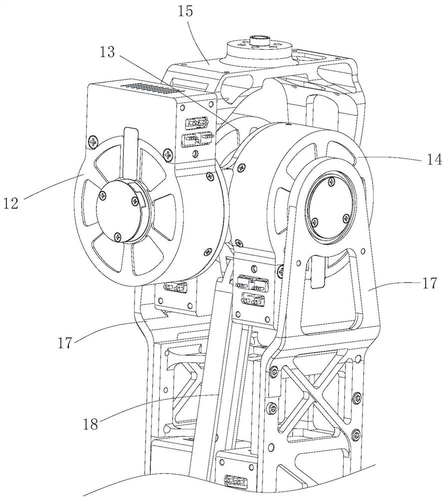
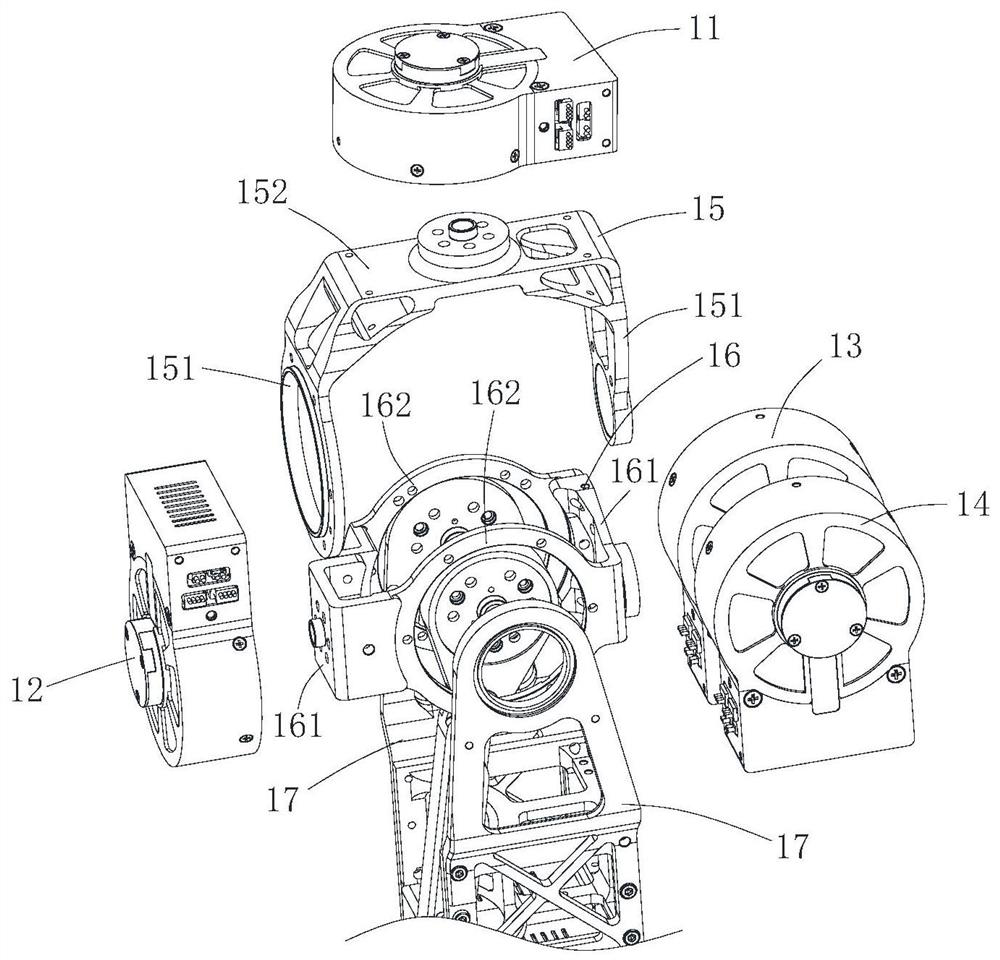
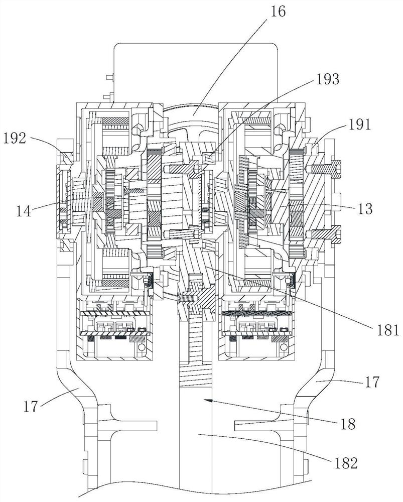
The invention provides a joint unit module and a leg robot, the joint unit module comprises a hip steering engine, a hip side steering engine, a hip front steering engine, a knee front steering engine, a thigh connecting rod structure, a thigh structural member, a first fixing frame and a second fixing frame, the hip steering engine, the hip side steering engine, the hip front steering engine and the knee front steering engine are all arranged at a hip joint; one end of the thigh connecting rod structure is fixed to an output shaft of the anterior knee steering engine, an output shaft of the hip steering engine is fixedly connected with the first fixing frame, a shell of the hip steering engine is fixed to the first fixing frame, an output shaft of the hip steering engine is fixedly connected with the second fixing frame, and the anterior hip steering engine and the anterior knee steering engine are both fixedly arranged on the second fixing frame. According to the joint unit module and the leg robot, on one hand, the structure of the joint steering engine is more concentrated, the structure is more compact, and the needed installation space is smaller, and on the other hand, the knee front steering engine is arranged to be high, the mass center of the leg robot can be increased, and the torque needed by the steering engine is reduced.

Description

technical field [0001] The invention belongs to the technical field of intelligent machinery, and more specifically relates to a joint unit module and a leg robot. Background technique [0002] Legged robots can be used in various application scenarios such as humanoid robots and industrial robots. Traditional leg robots usually connect the servos sequentially through a series scheme to form a leg of the robot, resulting in the traditional leg robot having the knee servo set at the knee joint and the ankle servo set at the ankle. Low center of mass, large moment of inertia, large steering gear torque, and difficult motion control. Contents of the invention [0003] The purpose of the embodiments of the present invention is to provide a joint unit module and a legged robot to solve the technical problems in the prior art that the center of mass of the robot is low and the torque required by the steering gear is large. [0004] In order to achieve the above object, the tec...

Claims


Application Information

Patent Timeline
IPC IPC(8): B62D57/032
CPCB62D57/032
Inventor 丁宏钰汪文广黄亮胡毅森
Owner UBTECH ROBOTICS CORP LTD
Learn More