


Quick Research
Generate reliable direction feasibility study reports for your R&D in just a few steps.

Technical Q&A
Discover and master advanced knowledge NOW. Basics, ideas, possibilities, all at once.

Find Solutions
As an expert in R&D theories, this can generate solutions to your technical problems instantly.

Evaluate Feasibility
Analyze your overall solution with one click, know your potential R&D risks in advance.

Monitor Landscape
Get weekly tech updates, stay abreast of the latest tech innovations and key insights.
Valve element and faucet
A valve core, water inlet technology, applied in the direction of sliding valve, multi-way valve, control valve, etc., to achieve the effect of increasing the function of connecting water, solving cold water flow, and low cost
- Summary
- Abstract
- Description
- Claims
- Application Information
AI Technical Summary
Problems solved by technology
Method used
Image

Examples
Embodiment 1
[0051] like Figure 5 As shown in the open state, the fixed part and the rotating part are covered figure 1 :
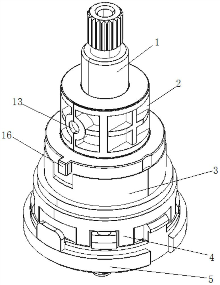
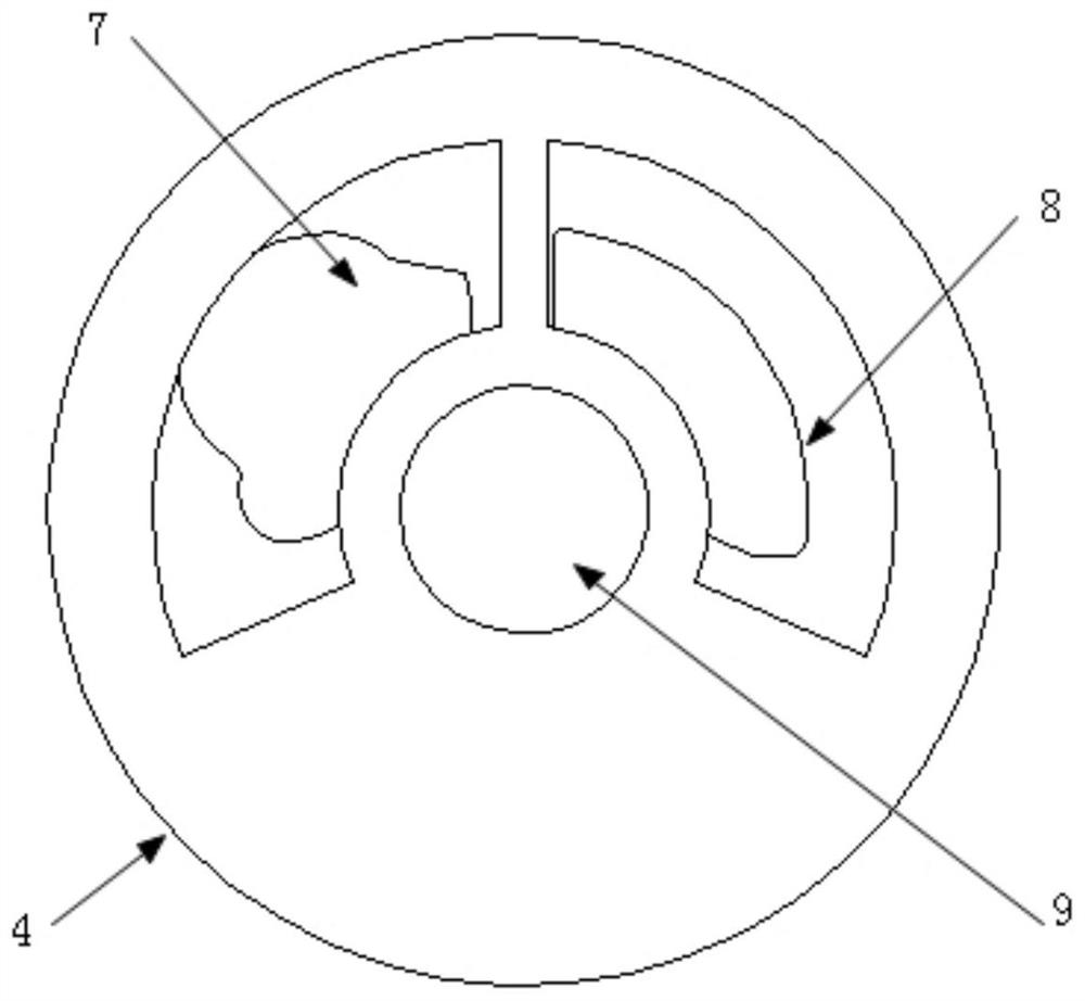
[0052] The rotating handle 1 drives the rotating connecting part 2 and the rotating part 3 to rotate: the outer side of the diversion groove 14 covers the first water inlet hole 7, the second water inlet hole 8, and the center of the diversion groove 14 covers the water outlet hole 9. Hot water state, at this time the communication groove 15 is far away from the first water inlet hole 7 and the second water inlet hole 8 .
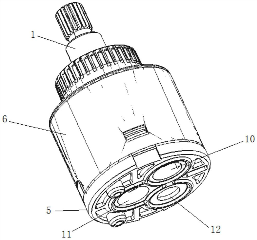
[0053] The hot water inlet of the faucet is connected to the first water inlet 10 of the front piece of the valve core, and the first water inlet 10 is connected to the first water inlet hole 7; the cold water inlet is connected to the second water inlet 11 of the front piece of the valve core, and the second water inlet 11 is connected to the second water inlet The water hole 8 and the water flow converge in the diversion groove 14 and then flo...
Embodiment 2
[0055] like Image 6 As shown, the schematic diagram of the cover of the fixed part and the rotating part in the closed state:
[0056] The rotating handle 1 drives the rotating connecting piece 2 and the rotating piece 3 to rotate to: the outer side of the connecting groove 15 covers the first water inlet hole 7 and the second water inlet hole 8. At this time, the center of the diversion groove 14 covers the water outlet hole 9, and the diversion groove 14 The outer side is away from the first water inlet hole 7 and the second water inlet hole 8, and the faucet is in a closed state.
[0057] The hot water inlet of the faucet is connected to the first water inlet 10 of the front piece of the valve core, and the first water inlet 10 is connected to the first water inlet hole 7; the cold water inlet is connected to the second water inlet 11 of the front piece of the valve core, and the second water inlet 11 is connected to the second water inlet In the water hole 8, the water f...
Embodiment 3
[0059] like Figure 7 As shown in the open state, the fixed part and the rotating part are covered figure 2 :
[0060] The rotating handle 1 drives the rotating connecting part 2 and the rotating part 3 to rotate: the outer side of the diversion groove 14 covers the first water inlet hole 7, the center of the diversion groove 14 covers the water outlet hole 9, and the faucet is in the hot water state. At this time, the connecting groove 15 It is away from the first water inlet hole 7 and covers the second water inlet hole 8 .
[0061] The hot water inlet of the faucet is connected to the first water inlet 10 of the front plate of the valve core, and the first water inlet 10 is connected to the first water inlet 7. Hot water passes through the diversion groove 14 and then flows out of the faucet outlet from the water outlet 9 and the water outlet 12.
PUM
 Abstract
Description
Claims
Application Information
 - R&D Engineer
- R&D Manager
- IP Professional
- Industry Leading Data Capabilities
- Powerful AI technology
- Patent DNA Extraction
Browse by: Latest US Patents, China's latest patents, Technical Efficacy Thesaurus, Application Domain, Technology Topic, Popular Technical Reports.
© 2024 PatSnap. All rights reserved.Legal|Privacy policy|Modern Slavery Act Transparency Statement|Sitemap|About US| Contact US: help@patsnap.com