Lifting equipment suitable for household use

A household and equipment technology, applied in the direction of lifting frame, lifting device, etc., can solve the problem of inconvenient lifting range extension, etc., achieve the effect of solving poor safety, good effect, and improving safety

Inactive Publication Date: 2021-09-21
CHANGSHU TONGRUN AUTO ACCESSORY
View PDF6 Cites 0 Cited by
  • Summary
  • Abstract
  • Description
  • Claims
  • Application Information

AI Technical Summary

Problems solved by technology

[0004] Aiming at the technical problems existing in the prior art, the present invention provides a lifting device suitable for home use to solve the problem that some existing lifting devices mentioned above are inconvenient to extend the overall lifting range when in use , and can no longer carry out the problem of secondary support before lifting

Method used


Image

  • Lifting equipment suitable for household use
  • Lifting equipment suitable for household use
  • Lifting equipment suitable for household use

Examples


Embodiment 1

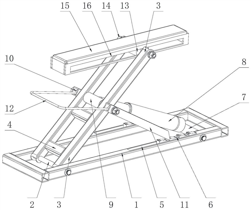
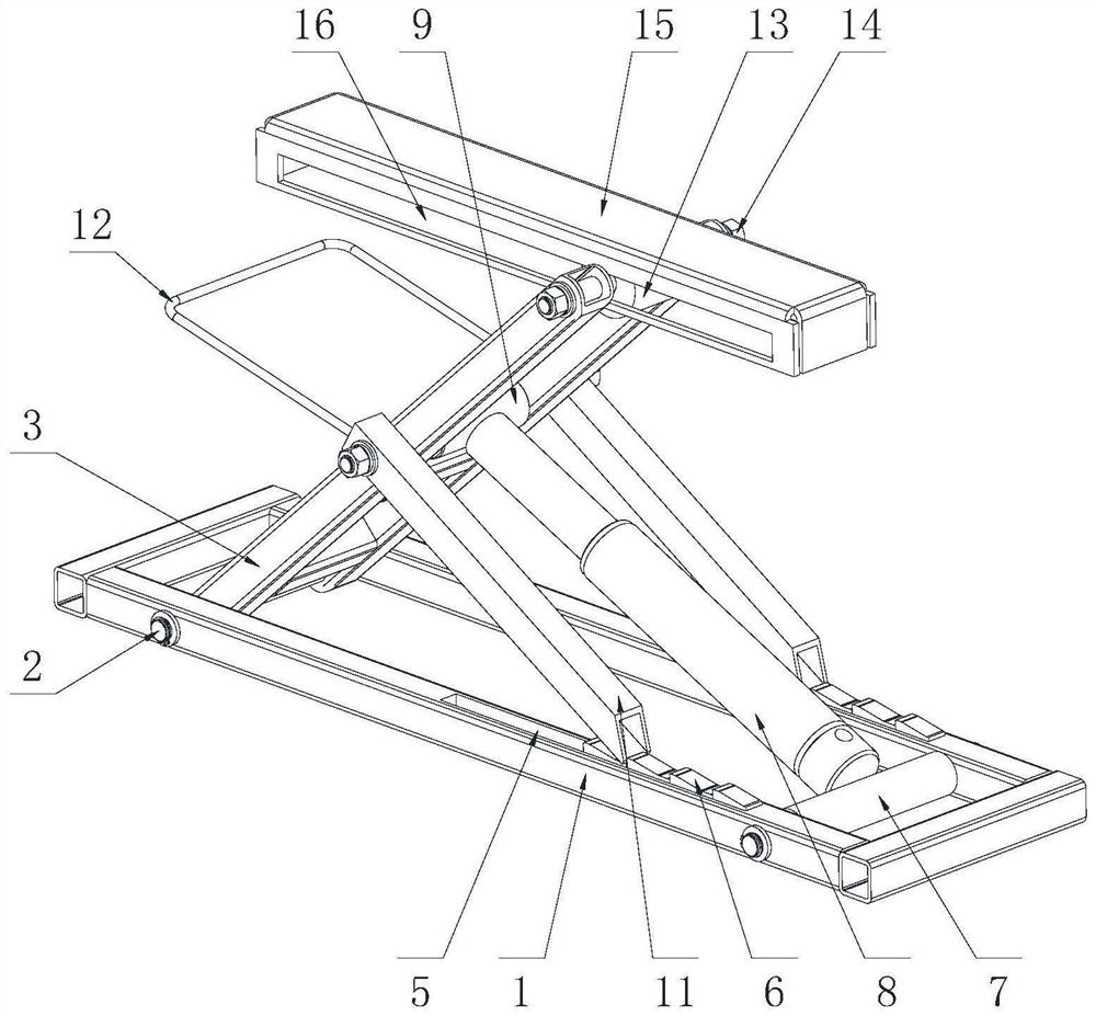
[0041] Such as Figure 1-3 As shown, a lifting device suitable for home use includes a base 1, an electric push rod 8 and an adjusting bolt 14. The front end of the base 1 is fixedly mounted with a first rotating shaft 2, and the outer side of the first rotating shaft 2 is rotatably connected to a first rotating plate. 3. A reinforcing plate 4 is fixed between the first rotating plate 3 and the adjacent first rotating plate 3; a card slot 5 is opened on the surface of the base 1, and a card block 6 is placed inside the card slot 5, and the rear side of the base 1 The second rotating shaft 7 is fixedly arranged, the surface of the second rotating shaft 7 is rotatably equipped with an electric push rod 8, the front end of the electric push rod 8 is fixedly installed with a drum 9, and the inside of the rotating drum 9 is fixedly connected with a third rotating shaft 10. Rotating shaft 10 is mounted on the first rotating plate 3, and both ends of the third rotating shaft 10 are p...

Embodiment 2

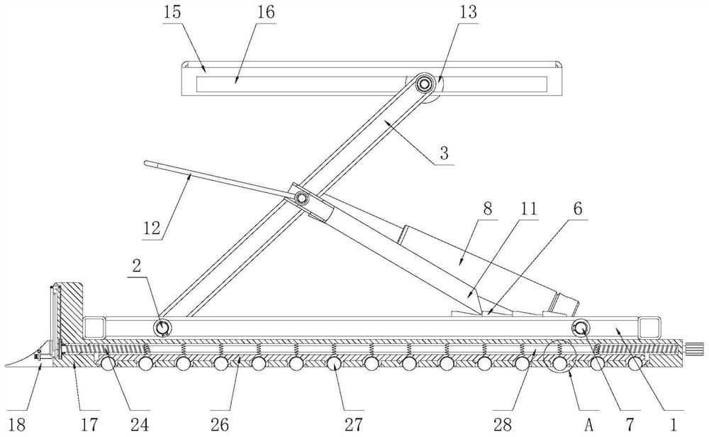
[0047] This example Figure 15-16 As shown, the difference between this embodiment and the first embodiment is that the block 6 in the first embodiment of the device can be replaced by a lowering wheel and a safety shaft to adjust the lifting height, and the lowering wheel is rotatably installed on the support At the end of the rod 11, the insurance shaft plays a role of support and protection. In addition, compared with the first embodiment, the third rotating shaft 10 and the safety lever 12 are not used.

[0048] It should be noted that the decline state such as Figure 15 As shown, the supporting state is as Figure 16 shown.

[0049] Concrete work process of the present invention is as follows:

[0050] (1) Adjust the support range

[0051] First, adjust the distance between two adjacent bases 1 according to the size of the object to be supported. By pulling one of the bases 1, the inscribed shaft 36 on one of the bases 1 rotates, and the first overlapping rod 35 By...


PUM


Abstract

The invention relates to the technical field of lifting equipment, in particular to household lifting equipment suitable for household use. The lifting equipment suitable for the household use comprises a base, an electric push rod and an adjusting bolt, a first rotating shaft is fixedly installed at the front end of the base, first rotating plates are rotationally connected to the outer side of the first rotating shaft, and reinforcing plates are fixedly arranged between the first rotating plate and the adjacent first rotating plate; a clamping groove is formed in the surface of the base, a clamping block is placed in the clamping groove, a second rotating shaft is fixedly arranged on the rear side of the base, the electric push rod is rotationally installed on the surface of the second rotating shaft, and a rotating cylinder is fixedly installed at the front end of the electric push rod. The lifting equipment suitable for the household use has the beneficial effects that the lifting equipment suitable for the household use is improved on the basis of an existing lifting equipment, supporting position and range are adjusted through a bearing assembly on the lifting equipment, protection effect can be achieved, the lifting equipment can conduct secondary bearing before and after supporting through a linkage structure, and the lifting equipment is more stable when an object is put down.

Description

technical field [0001] The invention relates to the technical field of lifting equipment, in particular to a lifting equipment suitable for home use. Background technique [0002] Lifting equipment is a commonly used tool in daily life. It mainly pushes the lifting plate upwards through the internal lifting mechanism to support objects upwards, which provides convenience for people’s equipment maintenance and daily life. However, the existing lifting equipment There are still some problems with the device in use: [0003] During the use of the existing lifting equipment, it is not convenient to adjust the position to be lifted according to the needs, it is difficult to extend the lifting range, and it cannot be supported before lifting, and the degree of adjustment is relatively low. , it is difficult to adapt to some objects with a relatively low chassis for supporting work, and it is also not conducive to subsequent stable placement, and when the existing lifting equipmen...

Claims


Application Information

Patent Timeline
Patent Type & Authority Applications(China)
IPC IPC(8): B66F7/06B66F7/28B66F7/02B66F9/12B66F9/20B66F9/075
CPCB66F7/0691B66F7/0641B66F7/0625B66F7/28B66F7/02B66F9/12B66F9/20B66F9/07586
Inventor 常良成曹志强谢毅沈韶阳
Owner CHANGSHU TONGRUN AUTO ACCESSORY
Why Eureka
Try Eureka