
Electronic product automatic tin soldering equipment

A technology for automating tin and electronic products, applied in welding equipment, auxiliary welding equipment, welding/cutting auxiliary equipment, etc., can solve problems such as increasing the difficulty of operation, reducing the operating efficiency of users, and achieving increased placement height, convenient operation and fixation The effect of positioning the body, increasing friction

Active Publication Date: 2021-09-21
南通诺澳电子有限公司
View PDF8 Cites 0 Cited by
  • Summary
  • Abstract
  • Description
  • Claims
  • Application Information

AI Technical Summary

Problems solved by technology

[0002] The existing automatic soldering machine mainly uses conventional fixing fixtures to clamp and fix the target circuit board. Because it uses conventional screw fixing methods, it needs to be operated with a wrench when it is loosely fixed and fixed. It needs to be searched and aimed at the target before normal operation can be carried out, which reduces the user's operating efficiency and increases the difficulty of operation, so a solution that can alleviate the above problems is urgently needed

Method used


Image

  • Electronic product automatic tin soldering equipment
  • Electronic product automatic tin soldering equipment
  • Electronic product automatic tin soldering equipment

Examples


Embodiment Construction

[0029] The technical solutions in the embodiments of the present invention will be clearly and completely described below in conjunction with the embodiments of the present invention. Apparently, the described embodiments are only some of the embodiments of the present invention, not all of them.

[0030] In the description of the present invention, it should be noted that the terms "upper", "lower", "inner", "outer", "front end", "rear end", "both ends", "one end", "another end" The orientation or positional relationship indicated by etc. is based on the orientation or positional relationship shown in the accompanying drawings, and is only for the convenience of describing the present invention and simplifying the description, and is used to improve the connection between the description and the drawings and to increase the clarity of the description, rather than Nothing indicating or implying that a referenced device or element must have a particular orientation, be construct...


PUM


Abstract

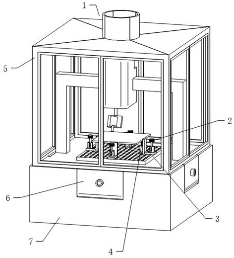
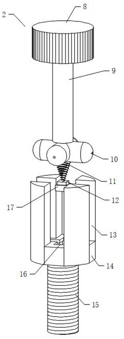
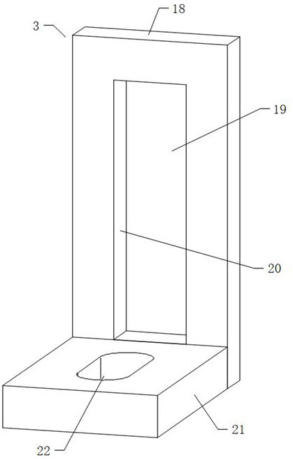
The invention discloses electronic product automatic tin soldering equipment comprising an automatic tin soldering machine, the automatic tin soldering machine comprises an operation main body, a positioning main body, a height adjusting main body, a protection main body, a binding seat and a machine body, the lower end of the operation main body and the machine body are installed together in a threaded mode, and the operation main body penetrates through the positioning main body in a sliding mode; the positioning main body is in movable contact with the machine body, the height adjusting main body and the positioning main body are fixedly installed together, the binding seat and the machine body are rotatably installed together, and the lower end of the protection main body is slidably inserted into the upper end of the binding seat; and the operation main body comprises a first knob, a connecting rod, a cross block, a spring, a connecting block, a first stop block, a second knob, a first bolt, a sliding groove and a sliding block, and the lower end of the first knob is fixedly connected with the connecting rod. The invention relates to the technical field of automatic tin soldering equipment, a user can conveniently adjust a clamp of the electronic product automatic tin soldering equipment, and the use requirement is better met.

Description

technical field [0001] The invention relates to the technical field of automatic soldering equipment, in particular to an automatic soldering equipment for electronic products. Background technique [0002] The existing automatic soldering machine mainly uses conventional fixing fixtures to clamp and fix the target circuit board. Because it uses conventional screw fixing methods, it needs to be operated with a wrench when it is loosely fixed and fixed. It needs to be searched and aimed at the target before normal operation can be carried out, thereby reducing the user's operating efficiency and increasing the difficulty of operation, so a solution that can alleviate the above problems is urgently needed. Contents of the invention [0003] The object of the present invention is to provide an automatic soldering equipment for electronic products, so as to solve the problems raised in the above-mentioned background technology. [0004] In order to achieve the above object, t...

Claims


Application Information

Patent Timeline
Patent Type & Authority Applications(China)
IPC IPC(8): B23K3/00B23K3/08B23K37/04
CPCB23K3/00B23K3/08B23K3/087B23K2101/42
Inventor 吴泽峰
Owner 南通诺澳电子有限公司
Learn More