


Quick Research
Generate reliable direction feasibility study reports for your R&D in just a few steps.

Technical Q&A
Discover and master advanced knowledge NOW. Basics, ideas, possibilities, all at once.

Find Solutions
As an expert in R&D theories, this can generate solutions to your technical problems instantly.

Evaluate Feasibility
Analyze your overall solution with one click, know your potential R&D risks in advance.

Monitor Landscape
Get weekly tech updates, stay abreast of the latest tech innovations and key insights.
Projection device for outdoor teaching
A projection device, horizontal technology, applied in educational appliances, electrically operated teaching aids, instruments, etc., can solve the problems of unclear viewing and strong light, etc.
- Summary
- Abstract
- Description
- Claims
- Application Information
AI Technical Summary
Problems solved by technology
Method used
Image

Examples
Embodiment 1
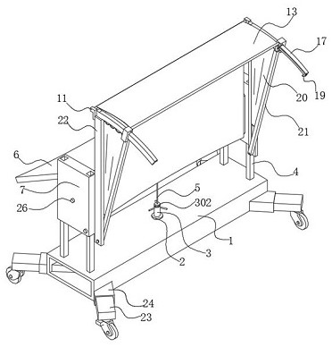
[0030] refer to Figure 1-Figure 5, a projection device for outdoor teaching, including a base 1 with a rectangular tubular structure that is placed horizontally as a whole. If the weight of the base 1 is not enough, a counterweight can be arranged on its lower surface to improve its stability. The base 1 The four corners of the lower surface of the bottom surface are provided with rollers that can extend diagonally in reverse, which increases the load-bearing area and improves the stability effect. The four corners of the upper surface of the base 1 are fixed with guide posts 4, and the top ends of the four guide posts 4 Two mutually parallel side guard plates 7 are slidably connected respectively, and a projection device is rotatably connected between the two side guard plates 7 , and the fronts of the two side guard plates 7 are respectively fixed with supporting slats parallel to each other in the vertical state. 22. The tops of the two supporting slats 22 are respectively...
Embodiment 2
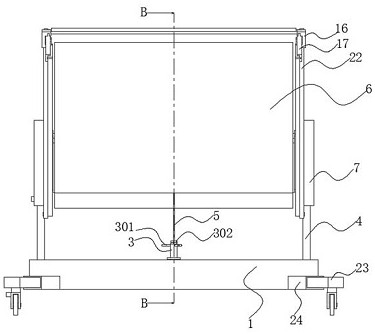
[0034] refer to Figure 6-Figure 8 , a projection device for outdoor teaching. Compared with Embodiment 1, this embodiment also includes a round hole in the middle of the upper surface of the base 1, and an adjusting threaded pipe 3 is rotatably connected to the round hole. The inner wall of the bottom of the base 1 A limit snap ring 25 adapted to the diameter of the adjustment threaded pipe 3 is fixed, and the outer wall of the adjustment thread pipe 3 is fixed on the upper surface of the base 1 and the lower surface of the limit snap ring 25 respectively with an annular retaining ring 2 and a retaining ring two. 26. The peripheral outer wall of the adjustment threaded pipe 3 is fixed with equidistantly distributed toggle rods 301 close to the top, the middle of the adjustment threaded pipe 3 is screwed with the limit ejector rod 5, and the lower surface of the side guard plate 7 is provided with the guide column 4. Adapted jack, the side of the side guard plate 7 is provided...
Embodiment 3
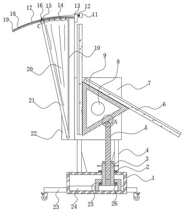
[0039] refer to Figure 9-Figure 10 , a projection device for outdoor teaching. Compared with Embodiment 1, on the basis of Embodiment 1, the top of the rotating bar 21 has a slot, and the slot is slidably connected with an extension push rod 15, and the extension push rod 15 is made of permanent magnet material, and there is a notch 1501 on the side of the extension rod 15 away from the curved screen 6, the inner wall of the notch 1501 is fixed with a locking block 1503, and the end of the limit groove 18 far away from the support slat 22 is fixed with the notch. 1501 compatible gear rod 19, the top of the extension push rod 15 is provided with a top ball 1502, and a compression spring is arranged between the bottom end of the extension push rod 15 and the groove bottom of the slot, so that the rotation bar 21 can be ensured when in use. Not going off the rails.
[0040] Wherein, the sliding block 16 comprises an upper block and a lower block slidably connected to the bottom...
PUM
 Abstract
Description
Claims
Application Information
 - R&D Engineer
- R&D Manager
- IP Professional
- Industry Leading Data Capabilities
- Powerful AI technology
- Patent DNA Extraction
Browse by: Latest US Patents, China's latest patents, Technical Efficacy Thesaurus, Application Domain, Technology Topic, Popular Technical Reports.
© 2024 PatSnap. All rights reserved.Legal|Privacy policy|Modern Slavery Act Transparency Statement|Sitemap|About US| Contact US: help@patsnap.com