Concrete raw material screening device for water conservancy project
A water conservancy project and screening device technology, which is applied in the direction of filter screen, solid separation, grid, etc., can solve the problems that the concrete strength cannot reach the standard, the service life of water conservancy project buildings is shortened, and the screening efficiency of concrete raw materials is low, so as to prevent the screening The effect of reducing efficiency, ensuring normal strength standards, and preventing blockage of screen holes
- Summary
- Abstract
- Description
- Claims
- Application Information
AI Technical Summary
Problems solved by technology
Method used
Image
Examples
Embodiment 1
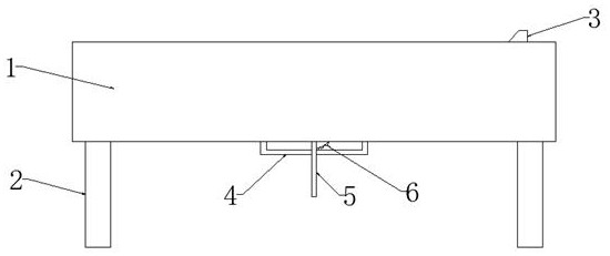
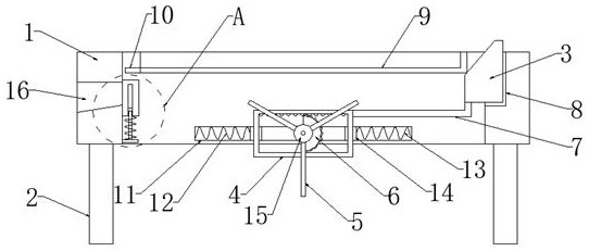
[0030] refer to figure 1 , figure 2 and Figure 4-7 , a concrete raw material screening device for water conservancy projects, comprising a frame 1, support legs 2 are fixedly installed at the four corners of the bottom end of the frame 1, and a screen frame 9 is installed on the inner rotation of the frame 1, and a screen mesh is installed on the inner wall of the screen frame 9 , and the side of the screen frame 9 away from the drive block 3 is open-shaped, and the side of the screen frame 9 away from the drive block 3 is fixedly connected with a material guide plate 10, the width of the material guide plate 10 is consistent with the width of the screen frame 9, And the top of material guide plate 10 and the top of sieve frame 9 internal screens are flush and arranged, and one side of frame 1 is fixedly installed with drive motor 22, and the output shaft end of drive motor 22 runs through the side wall of frame 1, and Extending to the inside of the frame 1 is fixedly conn...
Embodiment 2
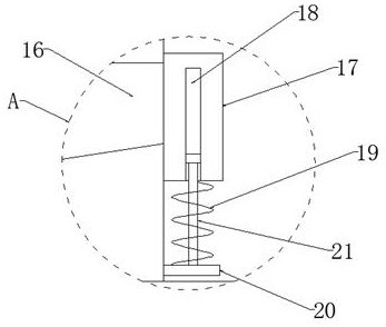
[0034] refer to figure 2 and image 3 , the inner wall of the frame 1 near the discharge port 16 is provided with an anti-leakage mechanism, the anti-leakage mechanism includes a baffle plate 17, a limit groove 18, a return spring 19, a fixed plate 20 and a limit rod 21, the inner side of the frame 1 A baffle 17 is slidably installed on the wall near the discharge port 16, and a limit groove 18 is provided inside the baffle 17. A fixed plate 20 is fixedly connected to the inner wall of the frame 1 near the side of the baffle 17, and the top of the fixed plate 20 is fixedly connected to the wall. There is a vertical stop bar 21, the end of the stop bar 21 is slidably installed in the inside of the stop slot 18, and a return spring 19 is fixedly connected between the bottom end of the baffle plate 17 and the top end of the fixed plate 20, and resets The spring 19 is sheathed on the rod body of the limiting rod 21 .
[0035] And when the screen frame 9 rotates, it will drive t...
Embodiment 3
[0037] refer to figure 1 , figure 2 and Figure 5-7 The side of the rotating plate 6 away from the output shaft of the drive motor 22 is fixedly connected with a rotating rod 15 distributed perpendicularly thereto, and the rod body of the rotating rod 15 is fixedly connected with a plurality of distribution plates 5 with the same structure.
[0038] When the driving motor 22 drives the rotating plate 6 to rotate, it will drive the rotating rod 15 to rotate, and the rotating rod 15 will drive the material distribution plate 5 to rotate, so that the material distribution plate 5 will evenly place the screened sand grains to prevent it from being located in a certain position. concentrated accumulation.
PUM
 Abstract
Description
Claims
Application Information
 - R&D
- Intellectual Property
- Life Sciences
- Materials
- Tech Scout
- Unparalleled Data Quality
- Higher Quality Content
- 60% Fewer Hallucinations
Browse by: Latest US Patents, China's latest patents, Technical Efficacy Thesaurus, Application Domain, Technology Topic, Popular Technical Reports.
© 2025 PatSnap. All rights reserved.Legal|Privacy policy|Modern Slavery Act Transparency Statement|Sitemap|About US| Contact US: help@patsnap.com


