
Camera module and electronic equipment

A camera module and camera technology, which is applied in televisions, electrical components, color TVs, etc., can solve the problems of large size and large number of PTZ modules

Inactive Publication Date: 2021-09-14
VIVO MOBILE COMM CO LTD
View PDF4 Cites 1 Cited by
  • Summary
  • Abstract
  • Description
  • Claims
  • Application Information

AI Technical Summary

Problems solved by technology

[0003] The purpose of this application is to provide a camera module and electronic equipment, at least to solve one of the problems of large size and large number of pan-tilt modules

Method used


Image

  • Camera module and electronic equipment
  • Camera module and electronic equipment
  • Camera module and electronic equipment

Examples


Embodiment Construction

[0027] Embodiments of the present application will be described in detail below, and examples of the embodiments are shown in the drawings, wherein the same or similar reference numerals denote the same or similar elements or elements having the same or similar functions throughout. The embodiments described below by referring to the figures are exemplary, and are only for explaining the present application, and should not be construed as limiting the present application. Based on the embodiments in this application, all other embodiments obtained by persons of ordinary skill in the art without creative efforts fall within the protection scope of this application.

[0028] The features of the terms "first" and "second" in the description and claims of the present application may explicitly or implicitly include one or more of these features. In the description of the present application, unless otherwise specified, "plurality" means two or more. In addition, "and / or" in the s...


PUM


Abstract

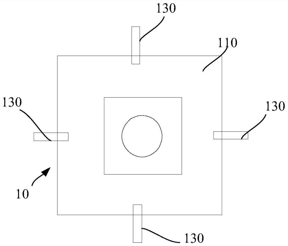
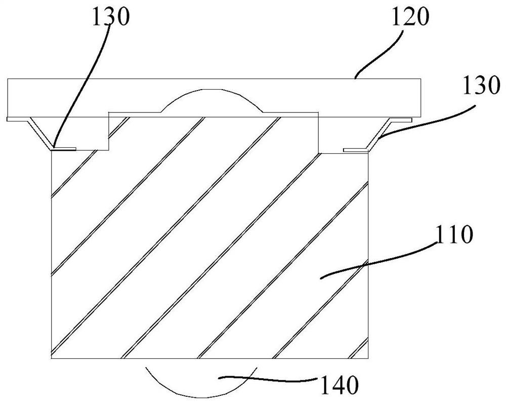
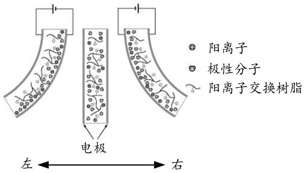
The invention discloses a camera module and electronic equipment, and belongs to the technical field of electronic equipment. The camera module comprises a camera body; a circuit board and the camera body are arranged at an interval; a plurality of electrically-induced deformation parts, wherein each electrically-induced deformation part is provided with a first end and a second end, the first end of each electrically-induced deformation part is connected with the camera body, the second end of each electrically-induced deformation part is connected with the circuit board, each electrically-induced deformation part is further electrically connected with the circuit board, and the electrically-induced deformation parts are arranged at intervals; wherein in the power-on state, the electrically-induced deformation piece deforms, and the distance between the camera body and the circuit board is shortened or increased.

Description

technical field [0001] The application belongs to the technical field of electronic equipment, and in particular relates to a camera module and electronic equipment. Background technique [0002] At present, smart phones are an indispensable product in people's life. In the current smart phone design, in order to meet the needs of taking pictures and anti-shake, major terminals introduce the pan-tilt technology into the camera. At present, the gimbal module adopts optical anti-shake, and the motor structure is complicated. Each direction mainly depends on the matching of magnets, coils, balls and other structures, and the bracket structure around the gimbal is used to achieve anti-shake. The entire module is large in size and has a large number of components. . Contents of the invention [0003] The present application aims to provide a camera module and electronic equipment, which at least solve one of the problems of large size and large number of pan-tilt modules. ...

Claims


Application Information

Patent Timeline
IPC IPC(8): H04N5/225
CPCH04N23/54H04N23/50H04N23/57
Inventor 李建伟
Owner VIVO MOBILE COMM CO LTD
Learn More