Welding machine plug

A kind of welding machine and plug technology, applied in the direction of fixed/insulated contact components, electrical components, coupling devices, etc., can solve the problems of lower production efficiency and assembly troubles

Pending Publication Date: 2021-09-14
广东联洋科技有限公司
View PDF0 Cites 0 Cited by
  • Summary
  • Abstract
  • Description
  • Claims
  • Application Information

AI Technical Summary

Problems solved by technology

[0002] The traditional welding machine plug generally includes an outer shell and a conductive component. The conductive component is passed through the outer shell, and a guiding plug-in structure is provided between the outer shell and the conductive component, so that the conductive component can be guided through the outer shell during assembly. shell, and can limit the relative rotation of the conductive component and the outer shell after being worn, but in the actual assembly process, due to the existence of the guiding plug structure, the conductive component needs to be inserted into the outer shell at a proper position, so the user needs to connect the conductive component with the outer shell. The outer casing is observed and compared, and the conductive component can only be inserted into the outer casing after the correct position is found, which leads to troublesome assembly and reduces production efficiency

Method used


Image

  • Welding machine plug
  • Welding machine plug
  • Welding machine plug

Examples


Embodiment Construction

[0026] Embodiments of the present invention are described in detail below, examples of which are shown in the drawings, wherein the same or similar reference numerals designate the same or similar elements or elements having the same or similar functions throughout. The embodiments described below by referring to the figures are exemplary only for explaining the present invention and should not be construed as limiting the present invention.

[0027] In the description of the present invention, it should be understood that when referring to orientation descriptions, such as terms "upper", "lower", "front", "rear", "left", "right", "vertical", "horizontal" ", "top", "bottom", "inner", "outer" and other indicated orientations or positional relationships are based on the orientations or positional relationships shown in the drawings, and are only for the convenience of describing the present invention and simplifying the description, rather than indicating Or imply that the devic...


PUM


Abstract

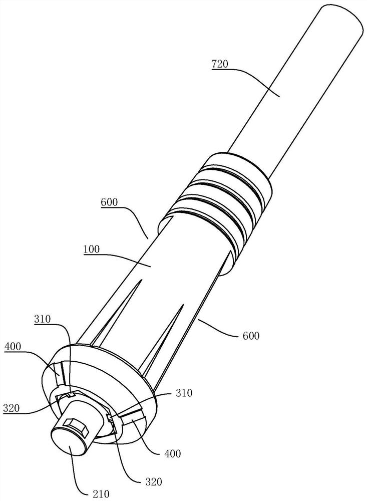
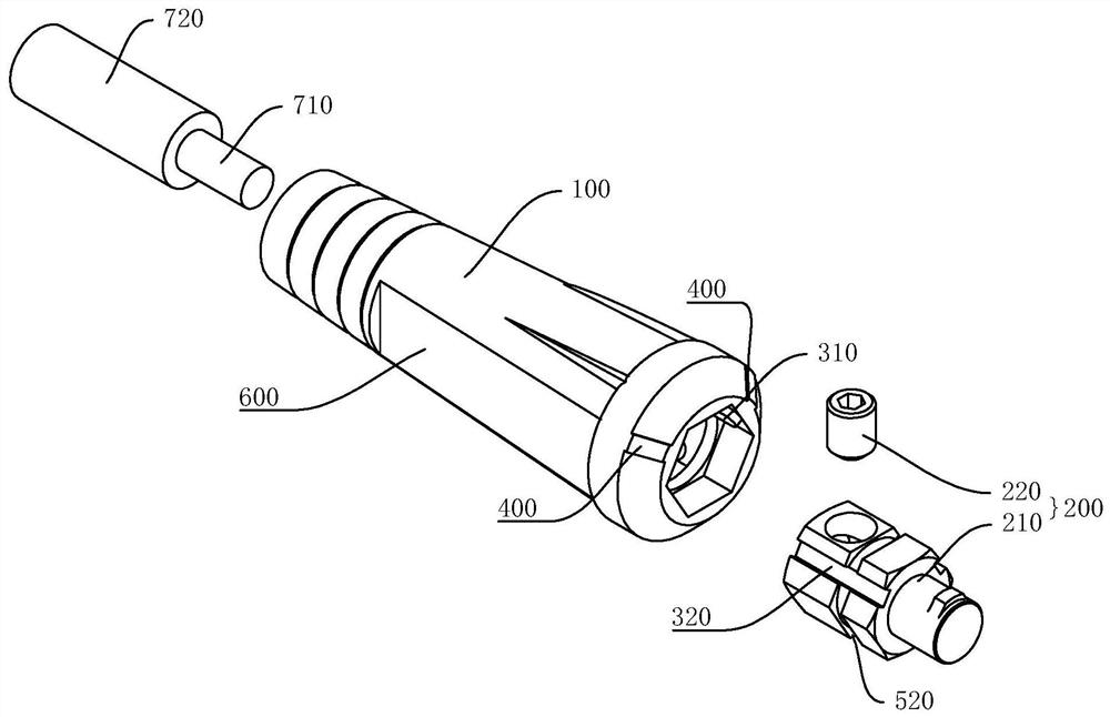
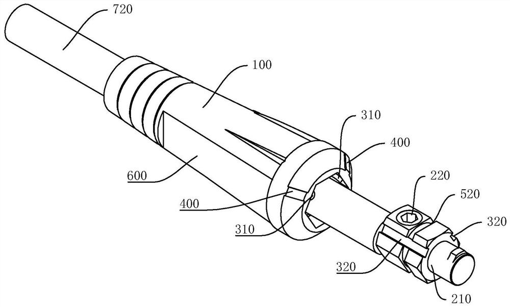
The invention relates to a welding machine plug. The welding machine plug of the present invention comprises an outer sleeve shell, a conductive assembly, a guide plugging structure and an identification assembly; the conductive assembly can be arranged in the outer sleeve shell in a penetrating manner; the guide plugging structure is arranged between the outer sleeve shell and the conductive assembly; the guiding plugging structure can guide the conductive assembly to penetrate through the outer sleeve shell and can limit relative rotation of the conductive assembly and the outer sleeve shell; the identification assembly is arranged on the outer sleeve shell to identify the plugging position of the conductive assembly relative to the outer sleeve shell; and when a user assembles the conductive assembly and the outer sleeve shell, a user can move the conductive assembly to a proper position relative to the outer sleeve shell according to the prompt of the plugging position identified by the identification assembly, so that the guide plugging structure between the outer sleeve shell and the conductive assembly can guide the conductive assembly to penetrate through the outer sleeve shell, assembly is simpler and more convenient, production efficiency is improved; and after the conductive assembly penetrates through the outer sleeve shell, the guide plugging structure can limit relative rotation of the conductive assembly and the outer sleeve shell, so that the connection is firm.

Description

technical field [0001] The invention relates to the technical field of welding machine accessories, in particular to a welding machine plug. Background technique [0002] The traditional welding machine plug generally includes an outer shell and a conductive component. The conductive component is passed through the outer shell, and a guiding plug-in structure is provided between the outer shell and the conductive component, so that the conductive component can be guided through the outer shell during assembly. shell, and can limit the relative rotation of the conductive component and the outer shell after being worn, but in the actual assembly process, due to the existence of the guiding plug structure, the conductive component needs to be inserted into the outer shell at a proper position, so the user needs to connect the conductive component with the outer shell. The outer casing is observed and compared, and the conductive component can only be inserted into the outer cas...

Claims


Application Information

Patent Timeline
Patent Type & Authority Applications(China)
IPC IPC(8): H01R13/40H01R13/629H01R13/641
CPCH01R13/40H01R13/629H01R13/641
Inventor 邹罗院张春榴
Owner 广东联洋科技有限公司
Why Eureka
Try Eureka