
Display panel and display device

A display panel and display layer technology, applied in electrical components, electric solid devices, circuits, etc., can solve the problems of poor camera shooting effect and inability to integrate camera modules in the display area of ​​the display panel

Active Publication Date: 2021-09-14
HEFEI VISIONOX TECH CO LTD
View PDF4 Cites 4 Cited by
  • Summary
  • Abstract
  • Description
  • Claims
  • Application Information

AI Technical Summary

Problems solved by technology

[0003] In related technologies, the display area of ​​the display panel cannot be integrated with functional components such as a camera module, and a notch area is usually set on the display panel to install the camera module, etc., that is, the display panel is usually a "notch screen", which is not truly comprehensive. Screen
When the camera module is arranged under the display panel, the screen-to-body ratio of the display panel can be increased, but the camera shooting effect is poor

Method used


Image

  • Display panel and display device
  • Display panel and display device
  • Display panel and display device

Examples


Embodiment Construction

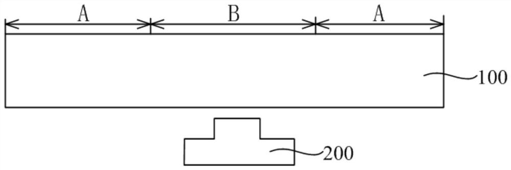
[0041] After long-term research, the inventor found that in related technologies, the camera module is usually integrated in the non-display area of ​​the display panel, the camera module is exposed, and the shooting effect of the camera module is better, but the display area of ​​the display panel is reduced. That is, the screen-to-body ratio of the display panel is reduced. When the camera module is arranged under the display panel, the screen-to-body ratio on the display panel increases, but it is difficult for external light to enter the area below the light-emitting unit of the display panel, and it is difficult for the camera module located in this area to receive enough light. As a result, the amount of light entering the camera module is low, which affects the shooting effect of the camera module.

[0042] In view of this, embodiments of the present invention provide a display panel and a display device. The display panel includes a main screen area and a secondary scr...


PUM


Abstract

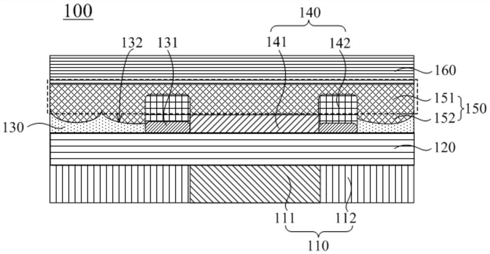
The invention provides a display panel and a display device, relates to the technical field of electronic equipment, and is used for solving the technical problem that the screen-to-body ratio of the display panel and the shooting effect of a camera module are difficult to consider at the same time, and the display panel comprises a main screen area and an auxiliary screen area; the display panel comprises a display layer, a touch control layer and a light-transmitting layer which are sequentially arranged in a stacked mode. The display layer comprises a plurality of light-emitting units and a pixel limiting layer for isolating the light-emitting units; and the side, close to the touch control layer, of the light transmitting layer located in the auxiliary screen area comprises at least one first lens part, the first lens part corresponds to the pixel limiting layer located in the auxiliary screen area and protrudes towards the touch control layer, the touch control layer comprises a first concave part embedded with the first lens part, and the refractive index of the first lens part is smaller than that of the touch control layer. Light can enter the touch layer with the large refractive index from the first lens part with the small refractive index, the first lens part with the protruding structure enables the area below the auxiliary screen area to receive more light, and the shooting effect of the camera module is improved.

Description

technical field [0001] The present invention relates to the technical field of electronic equipment, in particular to a display panel and a display device. Background technique [0002] With the development of display technology, a display device with a higher screen-to-body ratio can provide a better visual experience, and has gradually become a mainstream development direction, for example, a display device with a full screen. The full screen means that the front of the display panel in the display device is entirely a display area, that is, the screen-to-body ratio is close to 100%. [0003] In related technologies, the display area of ​​the display panel cannot be integrated with functional components such as a camera module, and a notch area is usually set on the display panel to install the camera module, etc., that is, the display panel is usually a "notch screen", which is not truly comprehensive. Screen. When the camera module is arranged under the display panel, ...

Claims


Application Information

Patent Timeline
Patent Type & Authority Applications(China)
IPC IPC(8): H01L27/32H01L51/52
CPCH10K59/40H10K50/85H10K50/865
Inventor 张强施文峰
Owner HEFEI VISIONOX TECH CO LTD
Learn More