Stall protection device based on centrifugal aerator

A protection device and aerator technology, applied in water aeration, sustainable biological treatment, water/sludge/sewage treatment, etc., can solve the problems of wear and tear of parts, shortened service life of centrifugal aerators, and too fast rotation speed.

Inactive Publication Date: 2021-09-14
济南梦嘉宏环保科技有限公司
View PDF3 Cites 1 Cited by
  • Summary
  • Abstract
  • Description
  • Claims
  • Application Information

AI Technical Summary

Problems solved by technology

[0006] Aiming at the deficiencies of the prior art, the present invention provides a stall protection device based on the centrifugal aerator, which can effectively reduce the rotating speed of the centrifugal aerator when the centrifugal aerator runs too fast to ensure a stable running speed, thereby increasing the speed of the centrifugal aerator. The advantage of the service life of the centrifugal aerator solves the problem that the centrifugal aerator is prone to excessive speed when it is running, which leads to serious wear of the internal parts and reduces the service life of the centrifugal aerator.

Method used


Image

  • Stall protection device based on centrifugal aerator
  • Stall protection device based on centrifugal aerator
  • Stall protection device based on centrifugal aerator

Examples


Embodiment 1

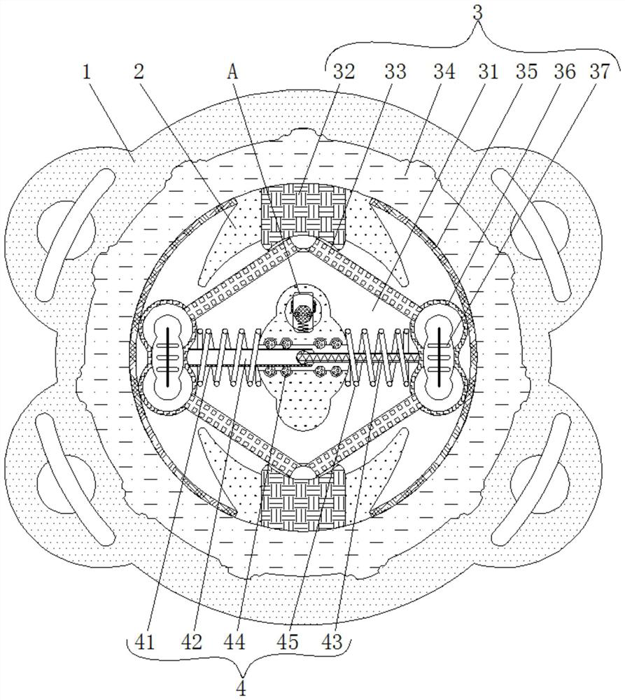
[0026] see figure 1 and figure 2 , a stall protection device based on a centrifugal aerator, including a main body 1, a rotating shaft 2, an actuator 3, a transmission mechanism 4 and a triggering mechanism 5, the inner side of the main body 1 is connected to the rotating shaft 2, and the inside of the rotating shaft 2 is movably connected to the actuator 3 and expand the rotating area of ​​the rotating shaft 2 during work, the actuator 3 includes a movable groove 31, an extension part 32, a connecting rod 33, a fluid groove 34, a metal sheet 35, an inner retracting part 36 and an electromagnet 37, and the inside of the rotating shaft 2 is provided There is a movable groove 31, which plays a role in facilitating the movement of the actuator 3, and the top and bottom of the rotating shaft 2 are movably connected with an extension piece 32 slidingly connected to the outside of the activity groove 31, and the shape of the extension piece 32 is a rectangle And the material of th...

Embodiment 2

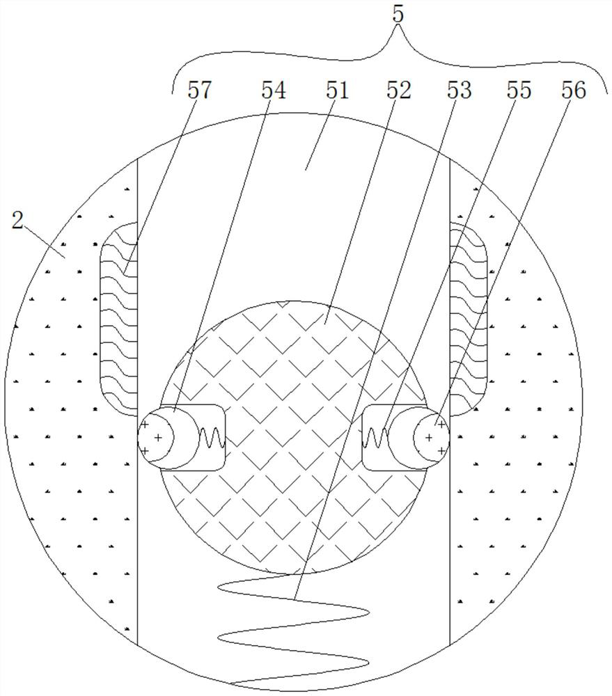
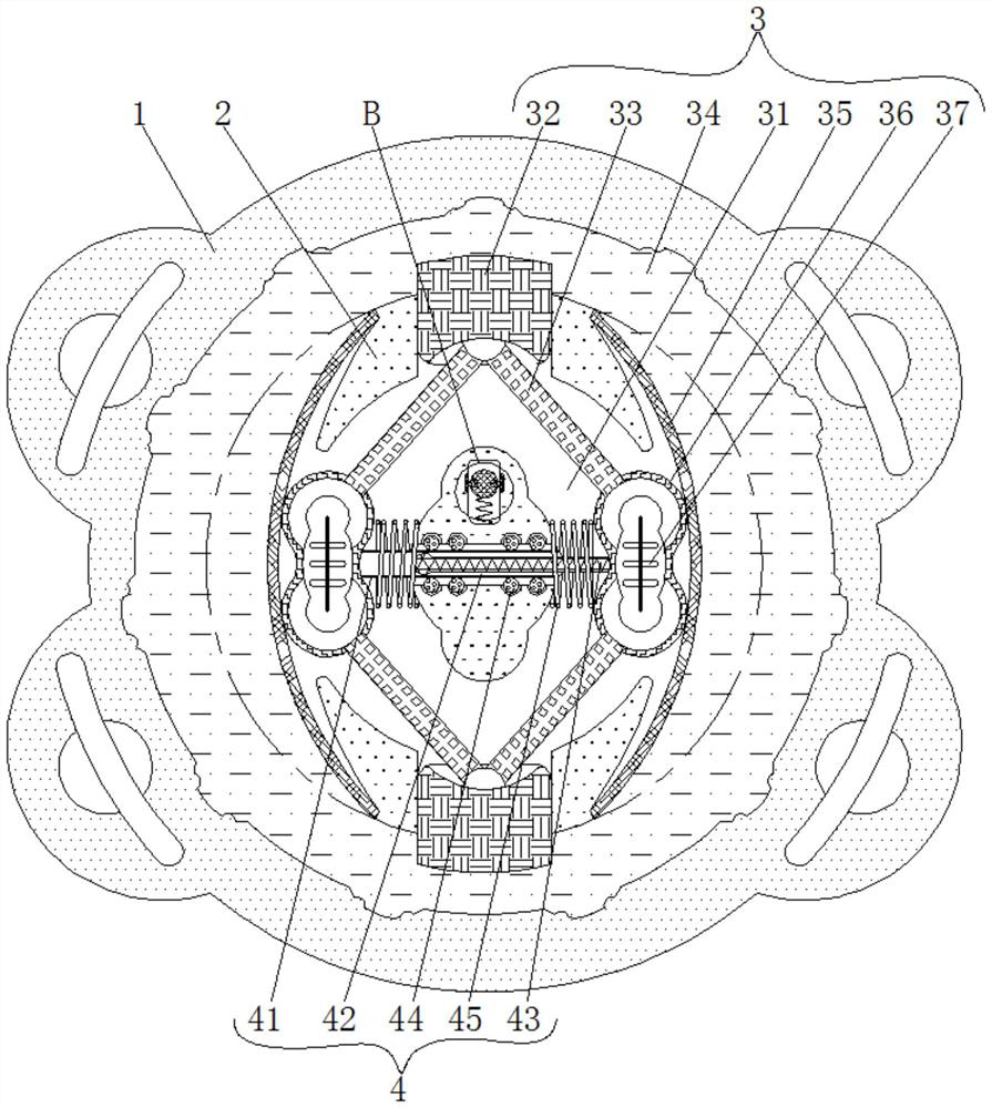
[0030] see Figure 1-4 , a stall protection device based on a centrifugal aerator, including a main body 1, a rotating shaft 2, an actuator 3, a transmission mechanism 4 and a triggering mechanism 5, the inner side of the main body 1 is connected to the rotating shaft 2, and the inside of the rotating shaft 2 is movably connected to the actuator 3 and expand the rotating area of ​​the rotating shaft 2 during work, the actuator 3 includes a movable groove 31, an extension part 32, a connecting rod 33, a fluid groove 34, a metal sheet 35, an inner retracting part 36 and an electromagnet 37, and the inside of the rotating shaft 2 is provided There is a movable groove 31, which plays a role in facilitating the movement of the actuator 3, and the top and bottom of the rotating shaft 2 are movably connected with an extension piece 32 slidingly connected to the outside of the activity groove 31, and the shape of the extension piece 32 is a rectangle And the material of the protruding...


PUM


Abstract

The invention relates to the technical field of environment-friendly materials, and discloses a stall protection device based on a centrifugal aerator; the stall protection device comprises a main body, a rotating shaft, an execution mechanism, a transmission mechanism and a trigger mechanism; the inner side of the main body is rotatably connected with the rotating shaft; and the interior of the rotating shaft is movably connected with the execution mechanism and is used for enlarging the rotating area of the rotating shaft during working. According to the stall protection device based on the centrifugal aerator, the rotating shaft drives the trigger mechanism to operate, and the transmission mechanism is matched with the trigger mechanism, so that when the rotating speed of the rotating shaft is too high, a circuit of the execution mechanism is switched on, the effect of driving an inner shrinkage piece to shrink towards the inner side is achieved, and the purpose of pushing an extension piece to extend towards the outer side is effectively achieved; therefore, the rotating area of the rotating shaft is increased, the rotating speed of the rotating shaft is effectively reduced under the obstruction of viscous liquid, the rotating shaft is in a stable rotating speed state, serious abrasion of internal parts of the aerator is avoided, and the service life of the centrifugal aerator is prolonged.

Description

technical field [0001] The invention relates to the technical field of environmental protection materials, in particular to a stall protection device based on a centrifugal aerator. Background technique [0002] Aerators can be divided into submersible jet aerators and centrifugal aerators according to their principles and uses. Aerators are mainly used for aeration and stirring of aeration tanks and aeration grit chambers in sewage treatment plants. Oxygenation and mixing of the mixed solution of sewage sludge, biochemical treatment of sewage or aeration of aquaculture and maintenance of landscape water, the centrifugal aerator is prone to excessive speed during operation, resulting in equipment friction problems. [0003] The centrifugal aerator is directly driven by the motor and the impeller, and the gas and water are fully mixed to form a uniform gas-water mixture. However, when the motor drives the impeller to run, the speed is often too fast, and the speed is too fast...

Claims


Application Information

Patent Timeline
Patent Type & Authority Applications(China)
IPC IPC(8): C02F7/00C02F3/02
CPCC02F7/00C02F3/02Y02W10/10
Inventor 高红飞
Owner 济南梦嘉宏环保科技有限公司
Why Eureka
Try Eureka