Agricultural intensive irrigation equipment with multi-angle adjusting function
An agricultural appliance, multi-angle technology, applied in the fields of agriculture and botany equipment and methods, applications, etc., can solve the problems of inability to adjust the irrigation angle, insufficient irrigation, and fixed irrigation range.
- Summary
- Abstract
- Description
- Claims
- Application Information
AI Technical Summary
Problems solved by technology
Method used
Image
Examples
Embodiment 1
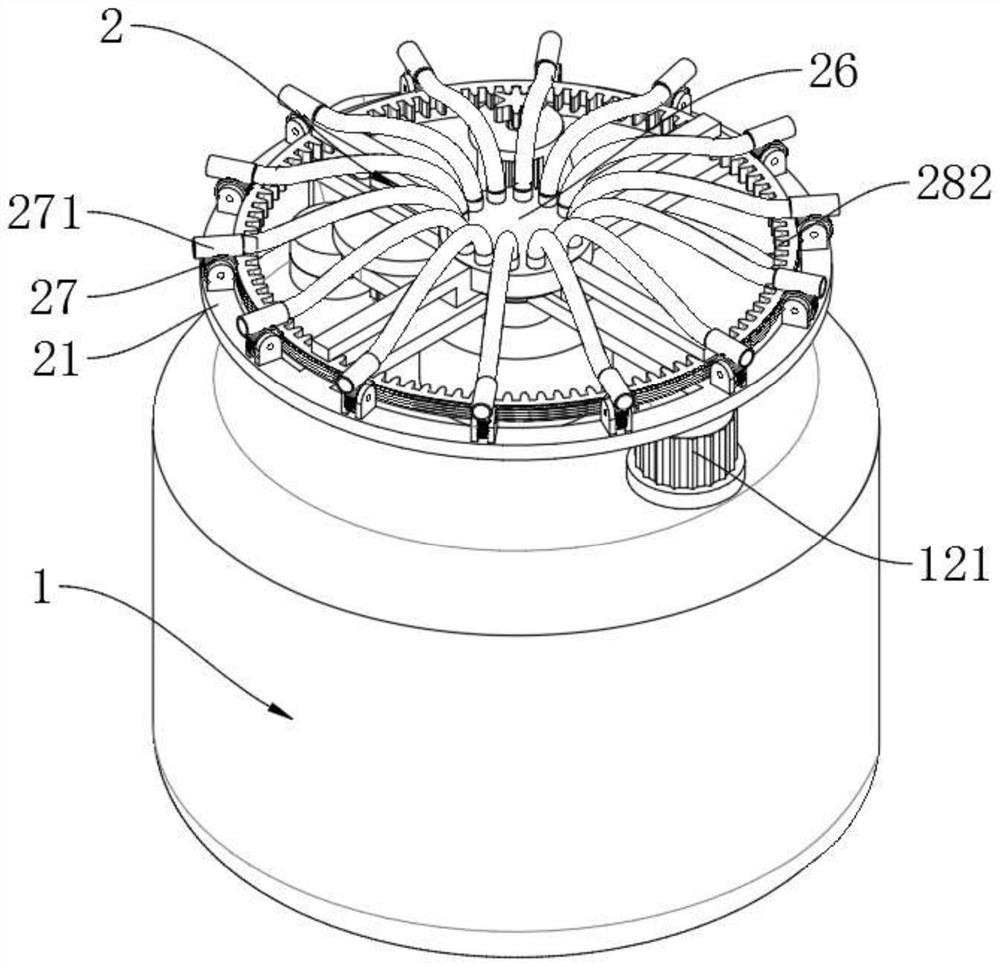
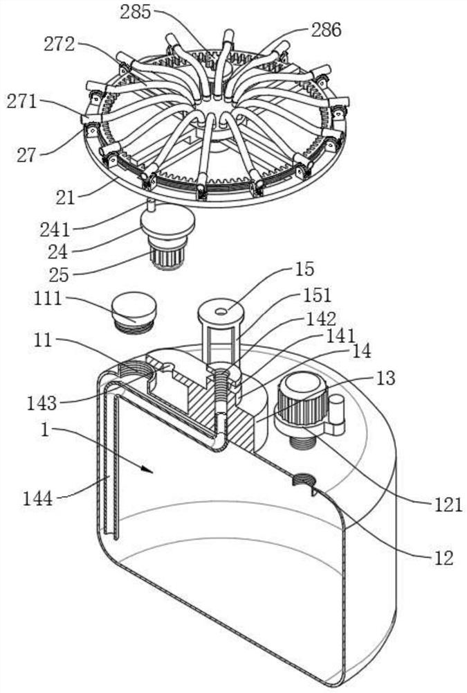
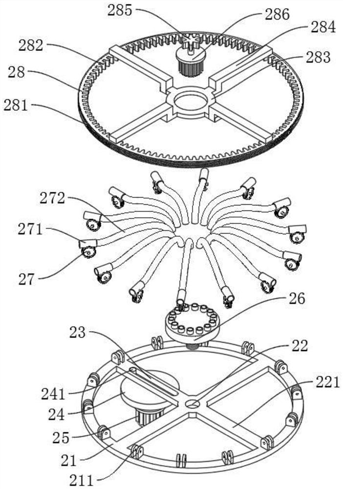
[0027] Example 1: See Figure 1~4 , in this embodiment, an agricultural intensive irrigation equipment with multi-angle adjustment function, comprising a water storage tank 1, a central fixed column 13 is fixed in the middle of the upper end of the water storage tank 1, and a central fixed column 13 is fixed in the middle of the top of the central fixed column 13. The rotating shaft boss 14 is provided with a rotating shaft slot 141 near the upper end of the rotating shaft boss 14. The rotating shaft boss 14 is penetrated with a threaded through hole 142, and the threaded through hole 142 communicates with the inner cavity of the water storage cylinder 1. The central fixed post 13 One side of the top is fixed with a motor fixing block 143, and the upper side of the water storage cylinder 1 is provided with a motor fixing plate 15, and between the motor fixing plate 15 and the water storage cylinder 1 are fixedly connected a number of fixed block connecting rods arranged at equa...
Embodiment 2
[0037] Example 2: see Figure 5-8 , the difference between this embodiment and embodiment 1 is:
[0038] In this embodiment, a bottom limit groove 161 is fixed in the middle of the inner bottom of the water storage cylinder 1, and a top limit groove 162 is provided in the middle of the inner cavity of the water storage cylinder 1 close to the upper end. A number of top limit groove connecting rods 163 arranged at equal intervals in the circumference are fixedly connected between the top ends of the top and bottom limit grooves 161. A stirring shaft 17 is fixed between the top limit groove 162 and the bottom limit groove 161, and a number of uniform Distributed rotating shaft stirring rods 171, the cylindrical surface near the upper end of the stirring shaft 17 is fixed with a number of card vertical sliders 172 arranged at equal intervals around the circumference, and the upper and lower ends of the card vertical slider 172 are fixed with limit plates 173 , the stirring rotat...
PUM
 Abstract
Description
Claims
Application Information
 - R&D
- Intellectual Property
- Life Sciences
- Materials
- Tech Scout
- Unparalleled Data Quality
- Higher Quality Content
- 60% Fewer Hallucinations
Browse by: Latest US Patents, China's latest patents, Technical Efficacy Thesaurus, Application Domain, Technology Topic, Popular Technical Reports.
© 2025 PatSnap. All rights reserved.Legal|Privacy policy|Modern Slavery Act Transparency Statement|Sitemap|About US| Contact US: help@patsnap.com


