Electric unlocking and counter locking mechanism

A technology for unlocking and driving mechanisms, applied in the field of electronic locks, can solve problems such as high energy consumption, no buffer design for the mechanism, and motor damage.

Pending Publication Date: 2021-09-10
SHENZHEN ZHIXIN IOT TECH CO LTD
View PDF0 Cites 0 Cited by
  • Summary
  • Abstract
  • Description
  • Claims
  • Application Information

AI Technical Summary

Problems solved by technology

[0002] Existing electronic locks realize unlocking and anti-locking by controlling the back and forth movement of the main tongue and oblique tongue, but the unlocking and anti-locking mechanisms of the current electronic locks are more complicated, and there are many transmission relationships, which affect the stability of unlocking and anti-locking, and consume more energy. Large; at the same time, when the existing electronic lock drives the internal mechanism to rotate through the motor, the motor needs to stop quickly after unlocking or anti-locking. The mechanism has no buffer design, which will cause great damage to the motor

Method used


Image

  • Electric unlocking and counter locking mechanism
  • Electric unlocking and counter locking mechanism
  • Electric unlocking and counter locking mechanism

Examples


no. 1 example

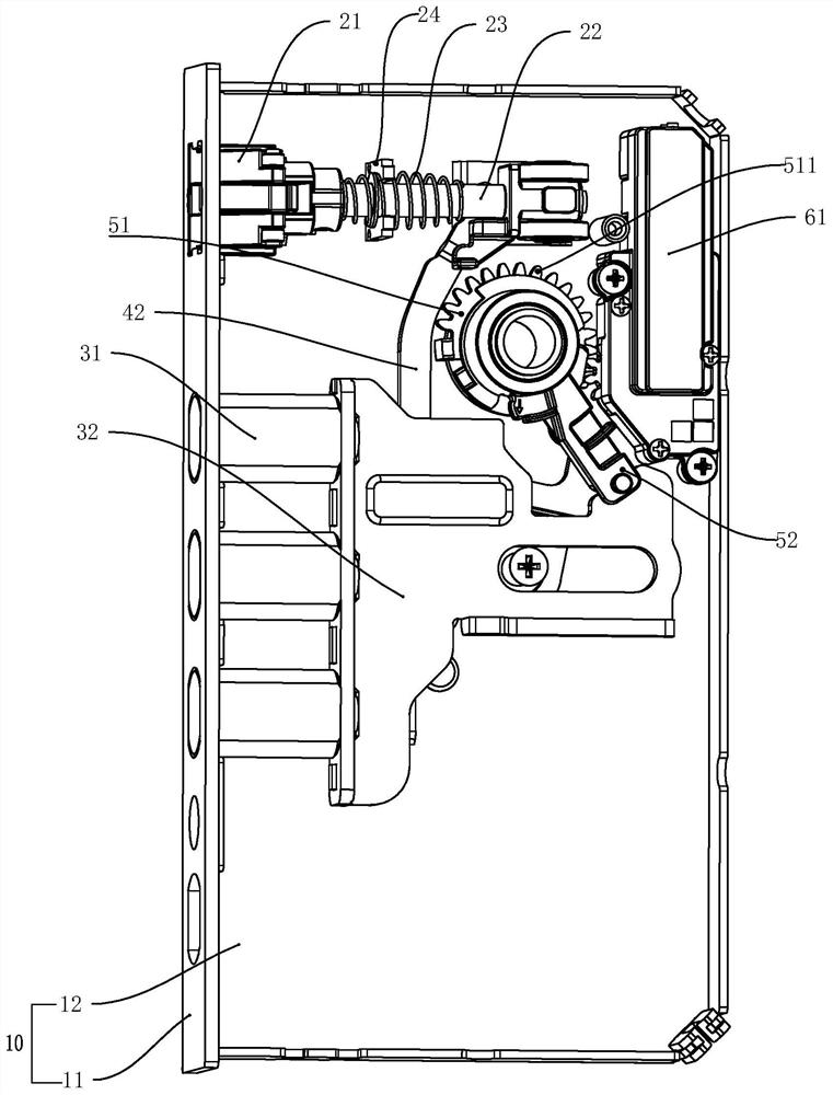
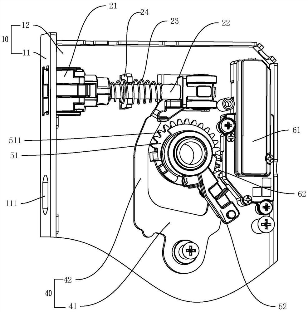
[0024] The first embodiment, such as Figure 1 to Figure 9 As shown, an electric unlocking and anti-locking mechanism includes a lock box 10, a bolt assembly 20, a main tongue assembly 30, a paddle assembly 40, a fork assembly 50 and a driving mechanism 60, and the lock box 10 includes a side plate 11 and a bottom plate 12. The side plate 11 is penetrated with a bolt hole and a main tongue hole 111; the bolt assembly 20 includes a bolt 21, a bolt connector 22 and a return spring 23 sleeved outside the bolt connector 22, and resets The spring 23 is in a compressed state, and the latch tongue 21 automatically stretches out of the latch tongue hole under the action of the return spring 23; the main tongue assembly 30 includes a main tongue 31 and a main tongue push plate 32, and one end of the main tongue push plate 32 is connected to the main tongue 31 is fixedly connected, and the other end is slidably connected with the bottom plate 12; the paddle assembly 40 includes a paddle...


PUM


Abstract

The invention discloses an electric unlocking and counter locking mechanism. The electric unlocking and counter locking mechanism comprises a lock box, a latch bolt assembly, a main bolt assembly, a shifting piece assembly, a shifting fork assembly and a driving mechanism, wherein the lock box comprises a side plate and a bottom plate; the latch bolt assembly comprises a latch bolt, a latch bolt connecting piece and a reset spring; the main bolt assembly comprises a main bolt and a main bolt push plate; the shifting piece assembly comprises a shifting piece body and a shifting rod; the shifting fork assembly comprises a turntable and a shifting fork push rod, and the turntable is provided with a driving rod; and the driving mechanism is used for pushing the turntable to rotate. When the driving mechanism drives the turntable to rotate in one direction, the turntable drives the main bolt assembly to move towards the inner side of the lock box through the shifting fork push rod, and the driving rod drives the latch bolt assembly to move towards the inner side of the lock box through the shifting rod. When the driving mechanism drives the turntable to rotate in the other direction, the turntable drives the main bolt assembly to move in the direction away from the inner side of the lock box through the shifting fork push rod, and the latch bolt automatically stretches out of a latch bolt hole under the action of the reset spring. The electric unlocking and counter locking mechanism has the advantages of being simple in structure, stable in transmission and capable of achieving rapid unlocking and counter locking.

Description

technical field [0001] The invention relates to the technical field of electronic locks, in particular to an electric unlocking and anti-locking mechanism. Background technique [0002] Existing electronic locks realize unlocking and anti-locking by controlling the back and forth movement of the main tongue and oblique tongue, but the unlocking and anti-locking mechanisms of the current electronic locks are more complicated, and there are many transmission relationships, which affect the stability of unlocking and anti-locking, and consume more energy. At the same time, when the existing electronic lock drives the internal mechanism to rotate through the motor, the motor needs to stop quickly after unlocking or anti-locking. The mechanism has no buffer design, which will cause great damage to the motor. Contents of the invention [0003] The purpose of the present invention is to solve the deficiencies of the prior art and provide an electric unlocking and anti-locking mec...

Claims


Application Information

Patent Timeline
Patent Type & Authority Applications(China)
IPC IPC(8): E05B47/00E05B63/14E05B15/10E05B15/00
CPCE05B47/0012E05B47/026E05B63/146E05B15/101E05B15/108E05B15/00E05B2047/0018E05B2047/002
Inventor 饶琴琴
Owner SHENZHEN ZHIXIN IOT TECH CO LTD
Why Eureka
Try Eureka