
PC board mounting mechanism

A technology of installation mechanism and PC board, which is applied in the direction of building construction, construction, and building material processing, etc., and can solve the problems of poor flexibility, high working intensity, and danger of end effectors

Pending Publication Date: 2021-09-10
SHANDONG TIANYI MACHINERY
View PDF0 Cites 1 Cited by
  • Summary
  • Abstract
  • Description
  • Claims
  • Application Information

AI Technical Summary

Problems solved by technology

PC board In the field of construction, PC board is the abbreviation of prestressed concrete prefabricated board components. It is an important board used for assembling buildings or partitions in buildings. Manual assembly by personnel is not only labor-intensive, but also has certain risks because it involves PC board posture adjustment and seam filling processes; in order to overcome the difficulties of PC board installation, some companies have launched PC board installation equipment. The actuator of the PC board installation equipment usually has three degrees of freedom, except for one degree of freedom which is manually adjusted and controlled, and the other two degrees of freedom are respectively controlled by two hydraulic cylinders. Due to the design problem of the actuator, not only the flexibility of the end effector is poor , and the coupling degree of the executive mechanism of the existing PC board installation equipment is high, the two hydraulic cylinders must be linked to control the translation of the PC board frame, which not only increases the complexity of the mechanism, but also increases the control cost of the hydraulic system

Method used


Image

  • PC board mounting mechanism
  • PC board mounting mechanism
  • PC board mounting mechanism

Examples


Embodiment Construction

[0020] The technical solutions of the present invention will be further described below through the accompanying drawings and embodiments.

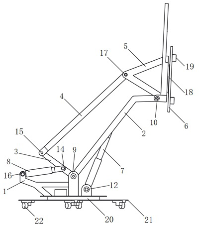
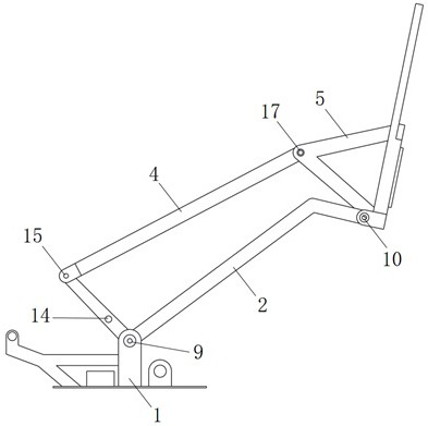
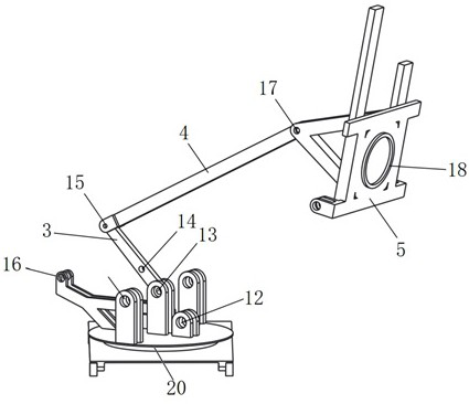
[0021] control figure 1 , figure 2 , image 3 , Figure 4 , Figure 5 , Figure 6 , a PC board installation mechanism, including a frame 1, a boom 2, a push rod 3, a pull rod 4, a support arm 5, a PC board frame 6, a boom cylinder 7, and a push rod cylinder 8, and the boom 2 includes the first A swivel pair 9, a second swivel pair 10, and a third swivel pair 11, the boom 2 is connected to the frame 1 through the first swivel pair 9, and one end of the boom cylinder 7 is connected to the frame through the fourth swivel pair 12 1, the other end is connected to the boom 2 through the third swivel pair 11, and the boom 2 is connected to the support arm 5 through the second swivel pair 10; the push rod 3 includes the fifth swivel pair 13, the sixth swivel pair 14. The seventh rotating pair 15, the push rod 3 is connected to the frame 1 ...


PUM


Abstract

The invention discloses a PC board mounting mechanism. The PC board mounting mechanism comprises a rack, a movable arm, a push rod, a pull rod, a supporting arm, a PC board frame, a movable arm oil cylinder and a push rod oil cylinder, the movable arm is connected with the rack through a rotating pair, and the movable arm can rotate relative to the rack under driving of the movable arm oil cylinder; the push rod is connected with the rack through the rotating pair, and the push rod can rotate relative to the rack under the driving of the push rod oil cylinder; the movable arm, the push rod, the pull rod and the supporting arm form a plane four-rod kinematic chain and form a parallelogram structure; the PC board frame is mounted on the supporting arm through the rotating pair; and in the lifting process of the movable arm, if the push rod oil cylinder does not work, the supporting arm keeps translational motion, that is, the PC board frame mounted on the supporting arm keeps translational lifting, the kinematics performance of existing PC board mounting equipment is effectively improved, and the mechanism coupling degree and the complexity of a hydraulic system are reduced. The PC board mounting mechanism is very suitable for carrying and mounting indoor partition PC boards.

Description

technical field [0001] The invention relates to the field of assembled building equipment, in particular to a PC board installation mechanism. Background technique [0002] The energy consumption of the construction industry accounts for about 30% of the total energy consumption of the society, and the steel consumption accounts for about 50% of the total steel consumption of the society. A large amount of construction waste is generated every year, and the problems of serious environmental pollution and high labor intensity have long existed. Therefore, the prefabricated building starting from industrial production and prefabricated construction is an important part of my country's "Manufacturing 2025 Plan". PC board In the field of construction, PC board is the abbreviation of prestressed concrete prefabricated board components. It is an important board used for assembling buildings or partitions in buildings. Manual assembly by personnel is not only labor-intensive, but a...

Claims


Application Information

Patent Timeline
Patent Type & Authority Applications(China)
IPC IPC(8): E04G21/16
CPCE04G21/167
Inventor 刘洪彬刘浩然林明星张林
Owner SHANDONG TIANYI MACHINERY
Learn More