A clamshell container structure
A container and clamshell technology, which is applied in the directions of packaging, transportation and packaging, launch/drag transmission, etc., can solve the problems of poor concealment and limited mobility of UAV launch, and achieve the effect of simple structure and high maneuverability
- Summary
- Abstract
- Description
- Claims
- Application Information
AI Technical Summary
Problems solved by technology
Method used
Image

Examples
Embodiment 1
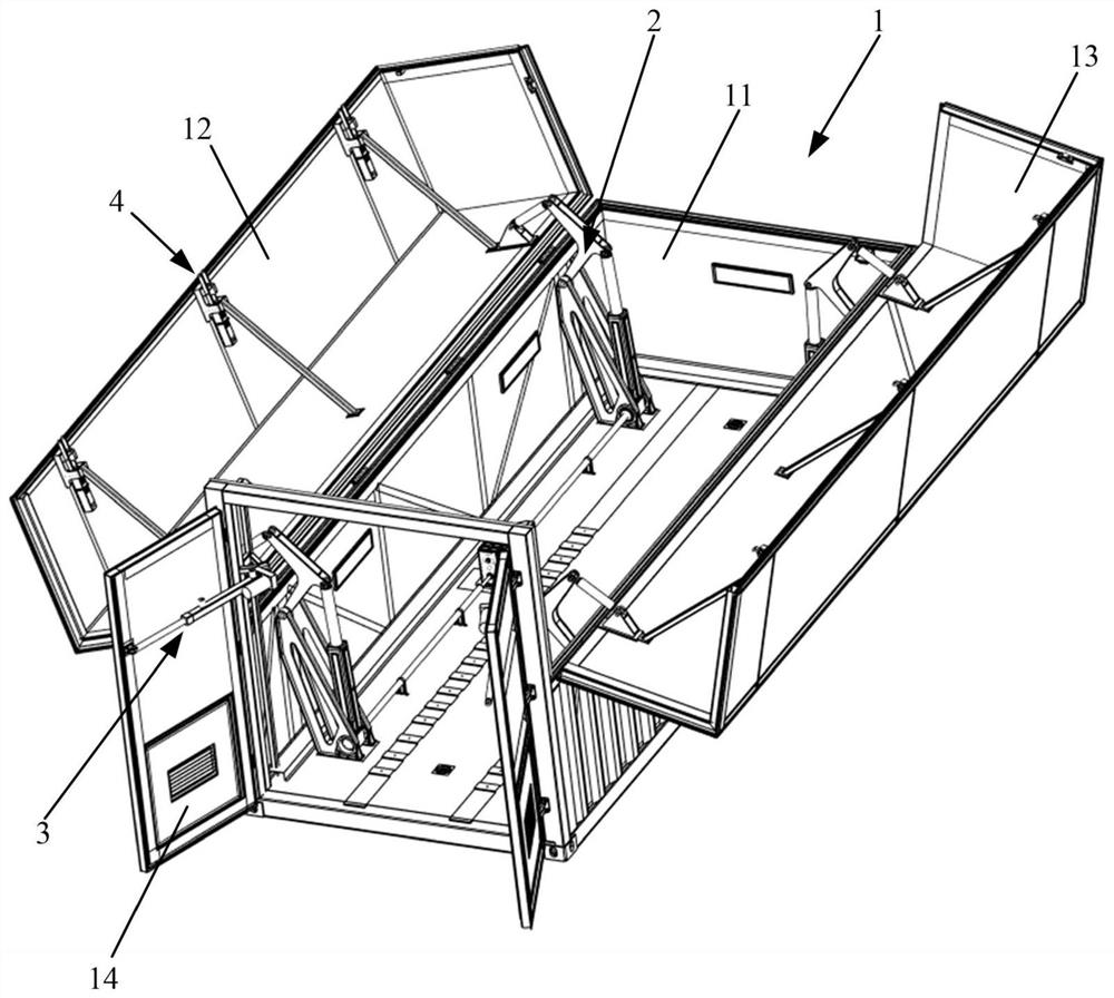
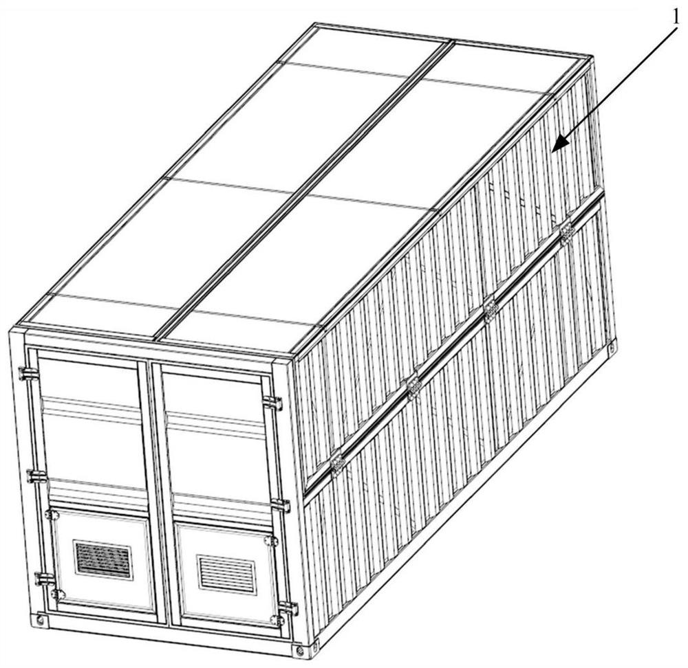
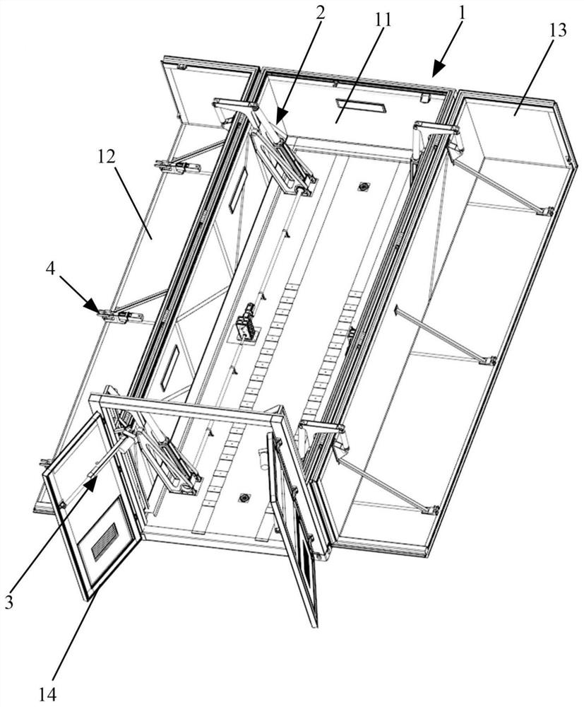
[0031] Such as figure 1 , figure 2 , image 3 as shown, figure 1 It is a structural view of the clamshell container structure; figure 2 It is a structural view of the fully closed state of the clamshell container structure; image 3 It is a structural view of the fully unfolded state of the clamshell container structure.
[0032] The clamshell container structure of the present invention includes a box body 1, a top cover flip mechanism 2, a door opening mechanism 3, and a guide locking mechanism 4; the box body 1 includes a bottom peripheral frame 11, a first flip top cover 12, a second flip Top cover 13, rear door 14; the first flip top cover 12 and the second flip top cover 13 are symmetrically arranged on the upper part of the peripheral frame 11, the first flip top cover 12, the second flip top cover The cover 13 , the rear door 14 and the bottom peripheral frame 11 are hinged.
[0033] The top cover turning mechanism 2 is arranged on the bottom peripheral frame 1...
Embodiment 2
[0046] Such as Figure 7 , Figure 8 as shown, Figure 7 Structural views of unfolding and closing respectively for the top cover turning mechanism; Figure 8 It is a structural view of the simultaneous unfolding and closing of the top cover turning mechanism; the top cover turning mechanism 2 includes a connecting seat, a fixed seat, a rotating seat, a push-pull rod, and the synchronous electric cylinder 22, and the fixed seat is fixed on the On the bottom plate, the fixed seat is connected to the rotating seat through a first rotating shaft, one end of the synchronous electric cylinder 22 is connected to the fixed seat in rotation, and the other end is connected to the rotating seat through a second rotating shaft, and the rotating The seat is rotatably connected to the connection seat through the push-pull rod, and the connection seat is fixedly arranged on the first reversible top cover 12 and the second reversible top cover 13 . The synchronous electric cylinder 22 pus...
Embodiment 3
[0051] Such as Figure 9 , Figure 10 , Figure 11 as shown, Figure 9 It is a structural perspective view of the guide locking mechanism; Figure 10 It is a structural view of the unlocked state of the guide locking mechanism; Figure 11 It is a structural view of the locking state of the guide locking mechanism. The guide locking mechanism 4 includes a first connection part and a second connection part, and the first connection part and the second connection part are respectively arranged on the first flip top cover 12 and the second flip top cover. 13, the first connecting part and the second connecting part are arranged in cooperation.
[0052] Specifically, the first connecting part includes a hook 43 and a guide block 44, and the second connecting part includes a clamping seat, a connecting rod group 42 and an electric push rod 41, and the electric push rod 41 is fixedly arranged on the card. On the socket, the end of the electric push rod 41 is movably connected t...
PUM
 Abstract
Description
Claims
Application Information
 - R&D
- Intellectual Property
- Life Sciences
- Materials
- Tech Scout
- Unparalleled Data Quality
- Higher Quality Content
- 60% Fewer Hallucinations
Browse by: Latest US Patents, China's latest patents, Technical Efficacy Thesaurus, Application Domain, Technology Topic, Popular Technical Reports.
© 2025 PatSnap. All rights reserved.Legal|Privacy policy|Modern Slavery Act Transparency Statement|Sitemap|About US| Contact US: help@patsnap.com