Combined ruler
A technology of combining ruler and square ruler, applied in the field of measuring tools, can solve the problem that it cannot be used to accurately detect the verticality of the facade.
- Summary
- Abstract
- Description
- Claims
- Application Information
AI Technical Summary
Problems solved by technology
Method used
Image
Examples
Embodiment 1
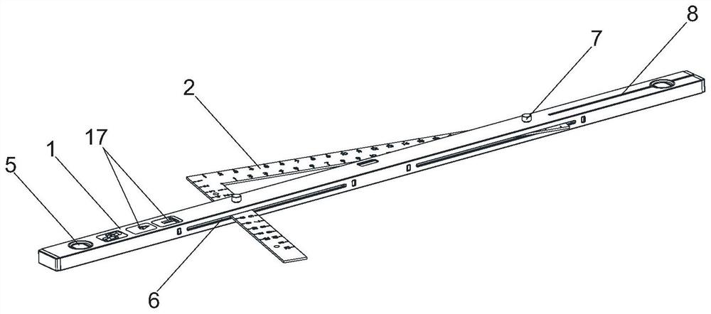
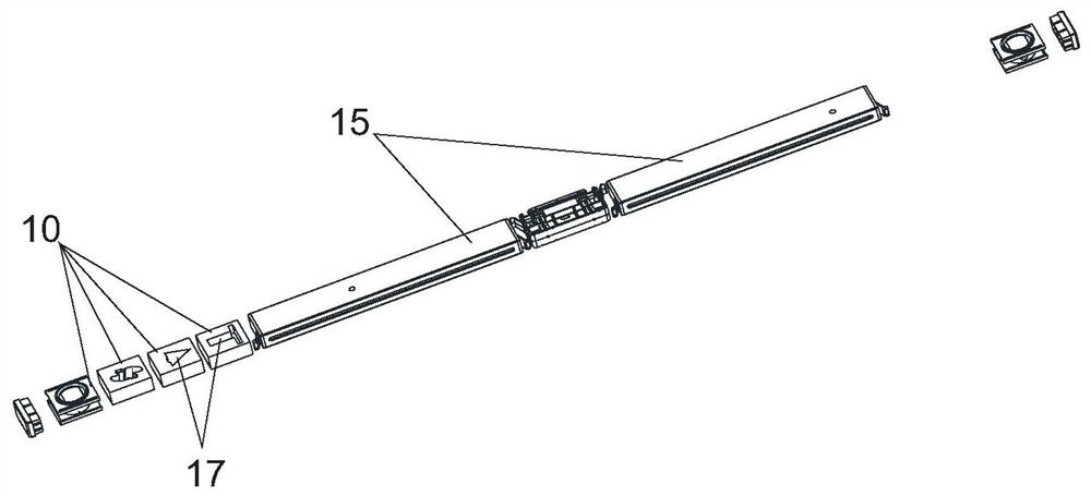
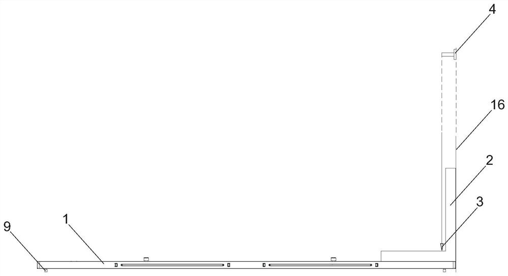
[0026] Such as Figure 1 to Figure 3As shown, a combination ruler includes a level ruler 1 and a verticality measurement component, and the verticality measurement component is accommodated on the level ruler 1 . The level ruler 1 is provided with three blister windows 5, which are located at the two ends and the middle side of the level ruler 1 respectively. The verticality measurement assembly includes a square 2, a plumb weight 3 and a plumb hanger 4, the square 2 is detachably connected to the level 1, and the level 1 is provided with a plumb assembly cavity 17, the plumb 3 and the plumb The hammer hanger 4 is placed in the cavity 17 of the plumb component. The side of the level 1 is provided with a square groove 6, the square groove 6 runs through the two sides of the level 1, the square 2 is embedded in the square groove 6, and the upper groove wall of the square groove 6 is provided with two through holes , The square 2 is also provided with two through holes, and the...
Embodiment 2
[0029] Such as Figure 4 to Figure 6 As shown, the combination ruler also includes a levelness measurement assembly, which includes a suspension block pole 11, a light emitter suspension block 12 and a light spot scale disc 13, and the suspension block pole 11 is hinged on the top of the level ruler 1 and the suspension block The turning angle range of the support rod 11 relative to the bottom surface of the level ruler 1 is 0-90°. The other end of the rod storage groove 14 is provided with a hanging block cavity, which is used to accommodate the light emitter hanging block 12. The light spot ruler disk 13 is located at the top of the level ruler 1 and is located on the same straight line as the pole storage groove 14. The light spot ruler disk 13, The support rod storage slot 14 is located on both sides of the root of the hanging block support rod 11, and the light spot scale disc 13 is marked with a scale. The free end of the hanging block pole 11 is provided with a cantile...
Embodiment 3
[0032] When measuring the verticality of the facade, the square 2 is placed on the bottom of the measured facade, and the square 2 is in close contact with the ground or the supporting surface of the facade and the measured facade at the same time, instead of using the level 1 as a base. All the other are with embodiment 1.
PUM
 Abstract
Description
Claims
Application Information
 - R&D
- Intellectual Property
- Life Sciences
- Materials
- Tech Scout
- Unparalleled Data Quality
- Higher Quality Content
- 60% Fewer Hallucinations
Browse by: Latest US Patents, China's latest patents, Technical Efficacy Thesaurus, Application Domain, Technology Topic, Popular Technical Reports.
© 2025 PatSnap. All rights reserved.Legal|Privacy policy|Modern Slavery Act Transparency Statement|Sitemap|About US| Contact US: help@patsnap.com


