a lifting column

A technology of lifting columns and columns, which is applied to the legs of general furniture, tables with variable table heights, household appliances, etc., can solve the problems of cumbersome installation process, difficult operation, poor user experience, etc., and achieve simple and convenient installation, The effect of stable structure and easy self-installation

Active Publication Date: 2022-04-29
NINGBO HAISHIKAI DRIVER TECH CO LTD
View PDF4 Cites 0 Cited by
  • Summary
  • Abstract
  • Description
  • Claims
  • Application Information

AI Technical Summary

Problems solved by technology

[0002] At present, the connection method between the lifting column and the ground foot of the existing traditional lifting table is usually fixed by fasteners such as screws. For end users who buy the lifting table, this installation method is too difficult to operate and the installation process is too cumbersome. and inconvenience, making the user experience poor

Method used


Image

  • a lifting column
  • a lifting column
  • a lifting column

Examples


Embodiment

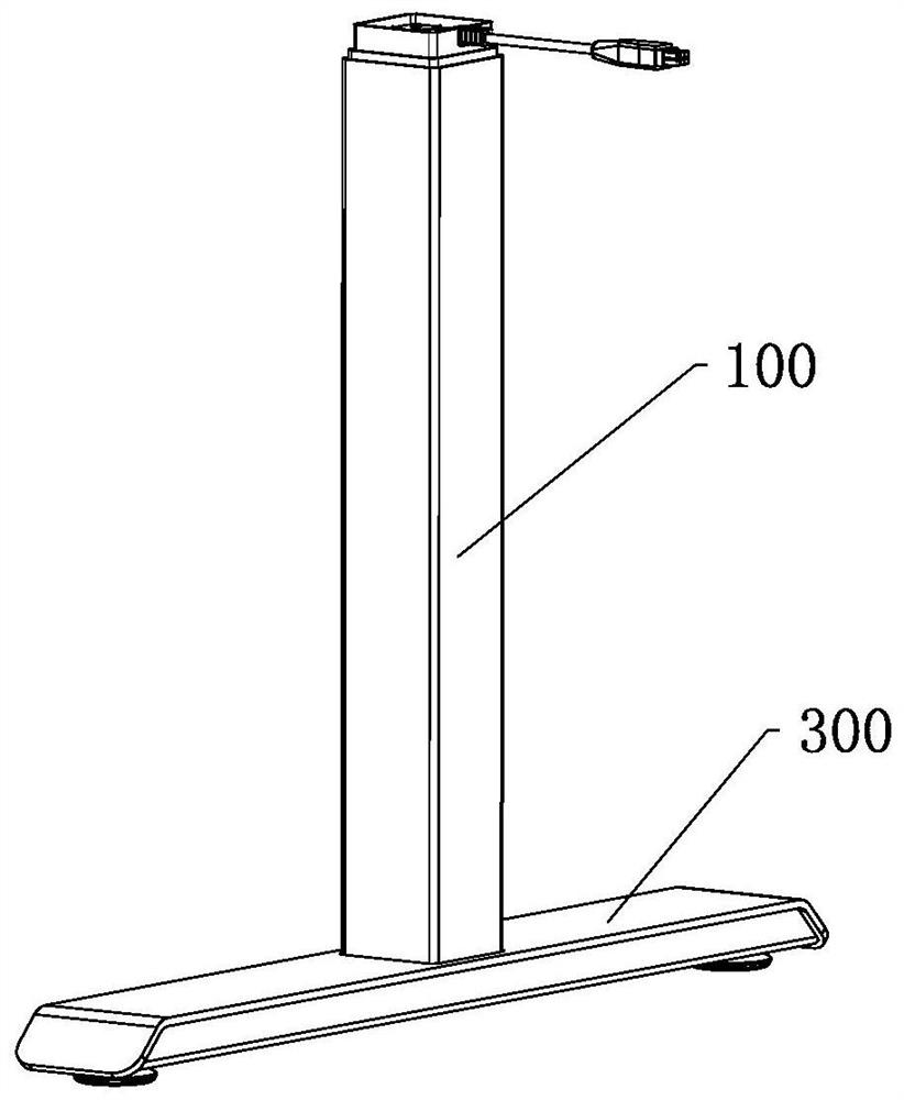
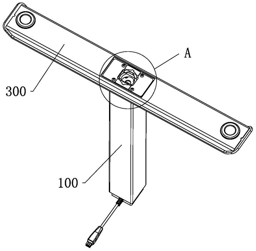
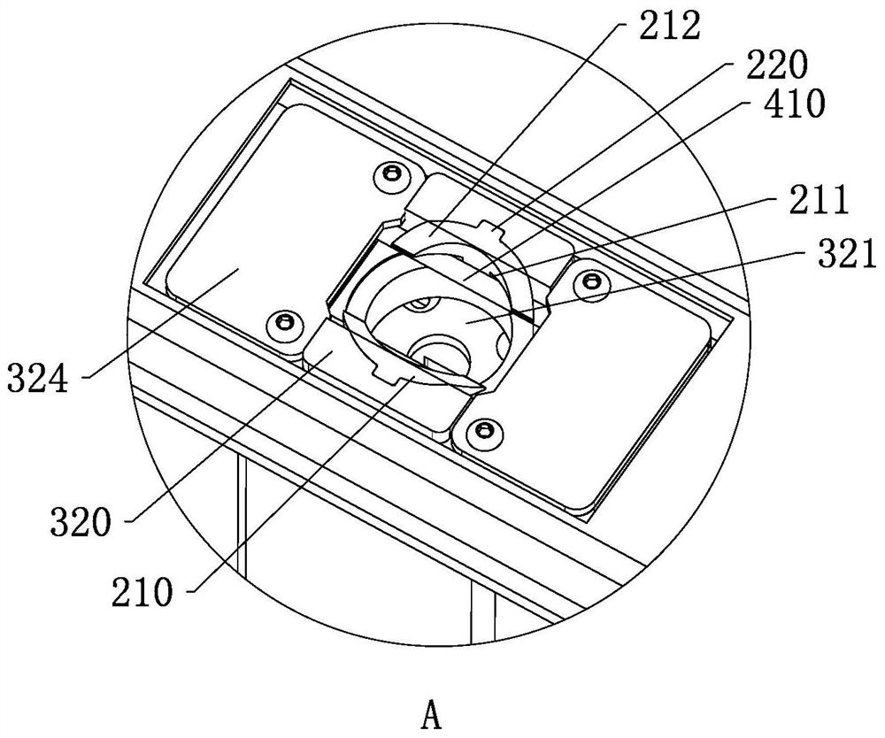
[0037] A lifting column, such as Figure 1 to Figure 10 As shown, it includes a column 100 and a foot 300 installed at the bottom of the column 100. A socket 200 is provided at the bottom of the column 100, a card slot 211 is provided on the socket 200, and a socket 211 is provided on the foot 300. The socket 321 of the socket 200 and the elastic clamping assembly 400 located at the lower part of the socket 321, when the column 100 is installed on the stand 300, align the socket 200 at the bottom of the column 100 with the socket 321 and insert it toward the socket 321. It can be plugged in the hole 321. During the plugging process, the connector 200 forms a squeeze on the elastic clamping component 400 in the socket 321 to push the elastic clamping component 400 away. When the connector 200 is installed in place, The elastic clamping assembly 400 resets under the action of the elastic force to be clamped in the slot 211 of the connector 200, and the elastic clamping assembly ...


PUM


Abstract

The invention discloses a lifting column, which comprises a column body and a support foot. The bottom of the column body is provided with a socket, and the socket is provided with a card slot. The foot includes a base and a socket, and the socket is provided with a The socket of the connector and the elastic clamping component located at the lower part of the socket are also provided with a guide slope. When the connector is inserted into the socket, the elastic clamping component is squeezed through the guide slope, and the insertion After the connector is installed in place, the elastic clamping component is clamped in the card slot to fix the column on the support foot. In the present invention, a socket is provided on the bottom of the column while a socket is provided on the leg, so that the column and the leg are fixed by the socket and the socket that are plugged together. The connecting component forms an extrusion. When the connector is installed in place, the elastic clamping component resets under the action of the elastic force to be clamped in the slot of the connector. The elastic clamping component cooperates with the slot to The connection is limited.

Description

technical field [0001] The invention belongs to the field of lifting devices, and in particular relates to a lifting column. Background technique [0002] At present, the connection method between the lifting column and the foot of the existing traditional lifting table is usually fixed by fasteners such as screws. For end users who buy the lifting table, this installation method is too difficult to operate and the installation process is too cumbersome. and inconvenience, making the user experience poor. Contents of the invention [0003] The technical problem to be solved by the present invention is to provide a lifting column to solve at least one of the above problems. [0004] In order to solve the above-mentioned technical problems, the present invention adopts the following technical scheme: a lifting column, including a column body and a foot mounted on the lower part of the column body, the bottom of the column body is provided with a connector, the connector is ...

Claims


Application Information

Patent Timeline
Patent Type & Authority Patents(China)
IPC IPC(8): A47B9/00A47B13/00A47B13/02
CPCA47B9/00A47B13/003A47B13/02
Inventor 叶董通龚旭良戎装晏张军生
Owner NINGBO HAISHIKAI DRIVER TECH CO LTD
Why Eureka
Try Eureka