A bearing ring inspection platform with reduced damage
A technology for testing platforms and bearing rings, which is applied to measuring devices, instruments, and the use of sound waves/ultrasonic waves/infrasonic waves to analyze solids, etc., can solve problems such as large wear on the outer wall of bearing rings, and achieve the goal of improving work efficiency, reducing wear, and increasing the degree of automation Effect
- Summary
- Abstract
- Description
- Claims
- Application Information
AI Technical Summary
Problems solved by technology
Method used
Image
Examples
Embodiment 1
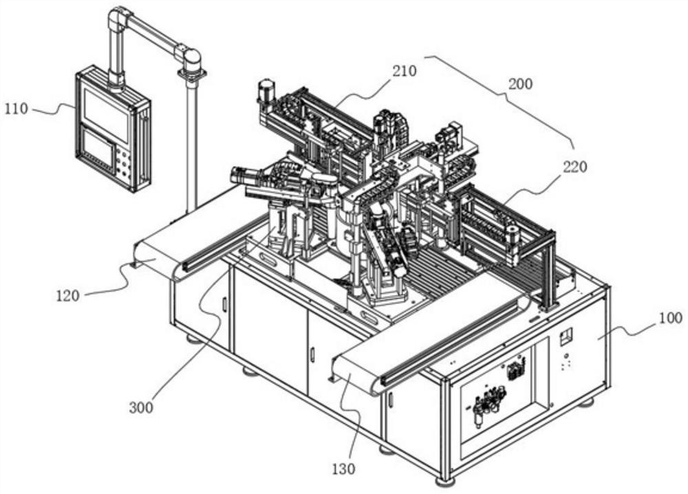
[0050] see figure 1 As shown, the purpose of this embodiment is to provide a bearing ring detection platform that reduces damage, including a bracket 100 and a detection platform 300 arranged on the top of the bracket 100, a control cabinet 110 is provided on one side of the bracket 100, and the two sides of the top of the bracket 100 A feeding conveyor belt 120 and an unloading conveyor belt 130 are respectively provided, and the detection table 300 is located between the loading conveyor belt 120 and the unloading conveyor belt 130. Please refer to Figure 4 with Figure 5 As shown, the detection station 300 includes at least:
[0051] The lifting liquid immersion component 310, the lifting liquid immersion component 310 includes a liquid immersion tank 311, and the coupling agent is injected into the liquid immersion tank 311, and its requirements are as follows:
[0052] Use distilled water or oil, hardness: 75mg / l; PH value: 6-9; purity: the maximum content of insoluble...
Embodiment 2
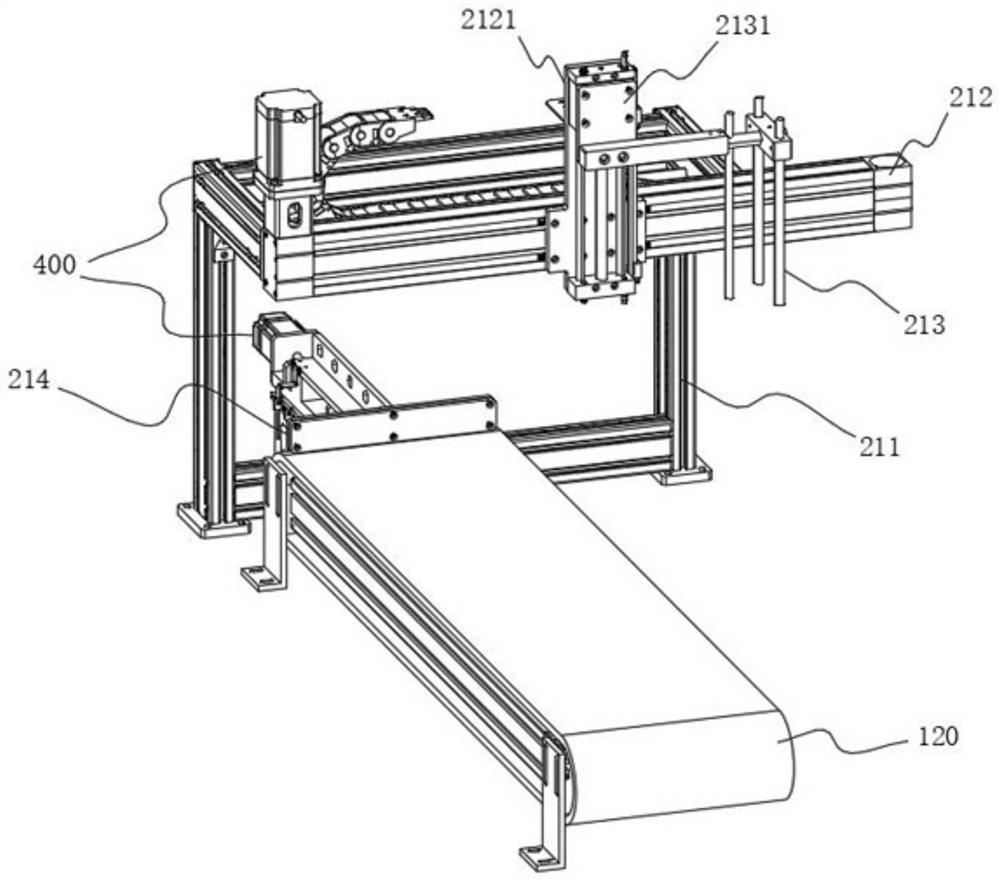
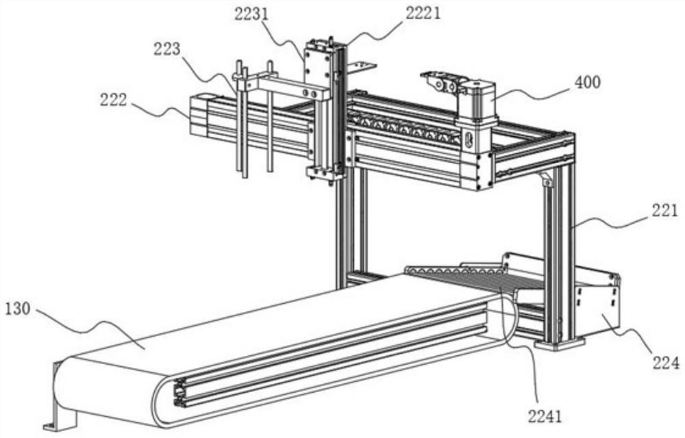
[0069] In order to facilitate the rapid lateral movement of the workpiece to be detected, the difference between this embodiment and Embodiment 1 is that, please refer to figure 2 with image 3 As shown, the traverse device 200 includes a feeding traverse assembly 210 and an unloading traverse assembly 220. The loading traverse assembly 210 is arranged on the side close to the feeding conveyor belt 120, and the unloading traverse assembly 220 is arranged near the unloading conveyor belt 120. One side of conveyor belt 130, wherein:
[0070] The feeding traversing assembly 210 includes a feeding traversing frame 211, the top of the feeding traversing frame 211 is provided with a feeding slide 212, and the feeding slide 212 is located on the feeding side and is provided with a feeding claw 213, and the feeding claw 213 One side near the feeding slide plate 212 is provided with a feeding longitudinal plate 2131, a feeding transverse plate 2121 is arranged between the feeding lon...
Embodiment 3
[0074] In order to limit the specified position and prevent the workpiece to be detected from deviating from the specified position, this embodiment is improved on the basis of Embodiment 2. Specifically: the top of the feeding traverse frame 211 is located at one end of the feeding conveyor belt 120. Limit plate 214, so that the designated position is limited by limit plate 214. In addition, limit plate 214 is slidably connected with feeding traverse frame 211, and is driven by drive assembly 400, and then the motor of drive assembly 400 and The screw rod cooperates with the driving limit plate 214 to move, so as to realize the adjustment of the limit position and improve the practicability of the limit plate 214 .
PUM
| Property | Measurement | Unit |
|---|---|---|
| thickness | aaaaa | aaaaa |
| height | aaaaa | aaaaa |
Abstract
Description
Claims
Application Information
 - R&D
- Intellectual Property
- Life Sciences
- Materials
- Tech Scout
- Unparalleled Data Quality
- Higher Quality Content
- 60% Fewer Hallucinations
Browse by: Latest US Patents, China's latest patents, Technical Efficacy Thesaurus, Application Domain, Technology Topic, Popular Technical Reports.
© 2025 PatSnap. All rights reserved.Legal|Privacy policy|Modern Slavery Act Transparency Statement|Sitemap|About US| Contact US: help@patsnap.com


