
Threading device and automatic threading equipment

A technology of threader and threader, which is applied in sewing equipment, embroidery machine mechanism, embroidery machine, etc., can solve the problems of automatic threading failure, affecting threading efficiency, troublesome operation, etc., to improve threading success rate, fast and convenient operation, The effect of low cost of use

Pending Publication Date: 2021-08-27
杭州衡论科技有限公司
View PDF0 Cites 2 Cited by
  • Summary
  • Abstract
  • Description
  • Claims
  • Application Information

AI Technical Summary

Problems solved by technology

When the existing equipment is disconnected, due to the rebound force of the spring on the machine head and the tension of the thread itself, the thread will rebound in a very short time, so that it will come out of the wire hole above the pinhole, and it is necessary to find the thread and re-thread it , The operation is troublesome. Some textile equipment uses automatic threaders, but because the thread is no longer in the correct position for automatic threading, it will cause automatic threading failure. For example, manual pulling and unwinding is required, which affects threading efficiency

Method used


Image

  • Threading device and automatic threading equipment
  • Threading device and automatic threading equipment
  • Threading device and automatic threading equipment

Examples


Embodiment 1

[0163] Embodiment one: if Figure 9 As shown, a needle threader includes a threading mechanism 40, a lead wire and a wire feeding mechanism, a calibration robot mechanism 80 and a thread hooking mechanism 90 on it. The thread pulling mechanism 40 is used to pull the sewing thread 14 down to a sufficient length for threading, and the lead wire And the thread feeding mechanism is used to guide the sewing thread 14 to the sewing needle to be threaded, the calibration robot mechanism 80 is used to adjust the position of the thread hooking mechanism 90 to align with the needle hole of the sewing needle, and the thread threading mechanism 90 is used to pass the sewing thread 14 through Sewing needle pinhole.

Embodiment 2

[0164] Embodiment two: if Figure 9 , Figure 15-17 and Figure 19-20 As shown, on the basis of Embodiment 1, the cable pulling mechanism 40 includes a driver fixing case 42 located on the installation base plate 32, a first driver 43 is fixed on one side of the driver fixing case 42, and the other side is sequentially arranged from top to bottom. A second driver 44, a third driver 45 and a fourth driver 46 are provided, and the movable ends of the first driver 43, the second driver 44, the third driver 45 and the fourth driver 46 extend into the driver In the fixed shell 42 and respectively connected with the first pull plate 47, the second pull plate 48, the third pull plate 49 and the fourth pull plate 410, the first pull plate 47, the second pull plate 48, the third pull plate 49 and the second pull plate The outer ends of the four pull-wire plates 410 protrude from the driver fixing case 42, and the inner surfaces of the outer ends of the first pull-wire plate 47 and th...

Embodiment 3

[0167] Example Three: Combining Figure 15-18 and Figure 21 As shown, on the basis of Embodiment 2, L-shaped connecting plates 412 are provided on both sides of the fixed housing 42 of the driving part, and a number of longitudinal strip holes 412.1 are provided on the bonding part of the connecting plate 412 and the mounting base plate 32, and the mounting base plate Corresponding positions on the 32 are provided with bottom plate strip-shaped holes 32.1 whose outer ends are inclined downward and are arc-shaped, and the back of the installation bottom plate 32 is provided with a fixed block 41 . A plurality of horizontal strip-shaped holes 412.1 are provided on the bonding portion of the connecting plate 412 and the fixed housing 42 of the driving element.

[0168] Wherein, there is a fixed shell hole 32.2 in the middle of the installation bottom plate 32 for the driver fixed shell 42 to pass through, and the fixed shell hole 32.2 is fan-shaped with a wide top and a narrow ...


PUM


Abstract

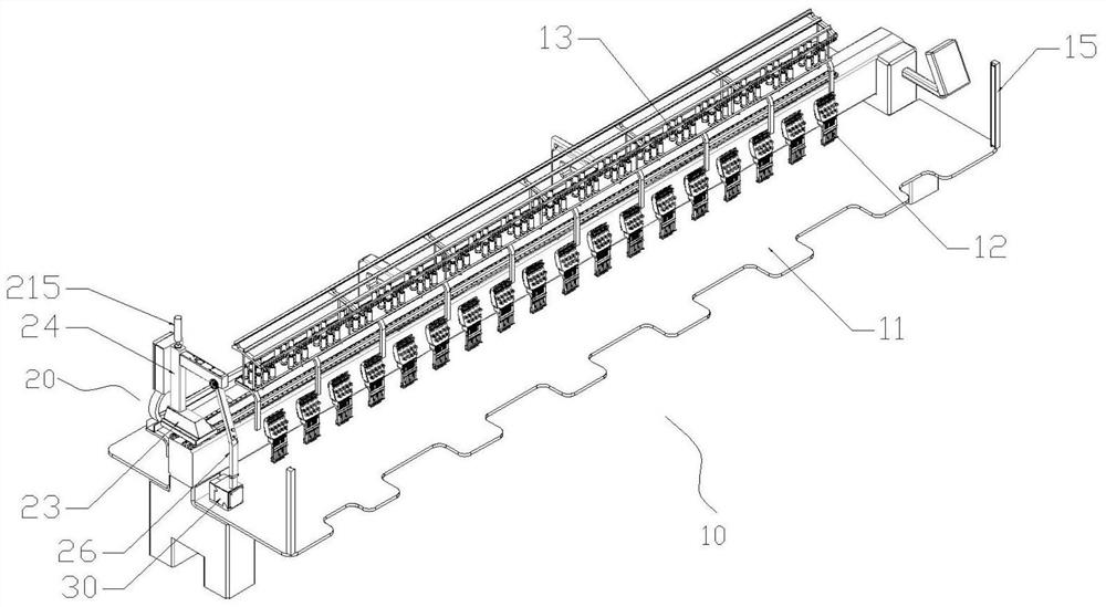
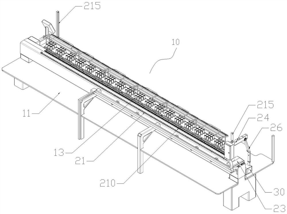
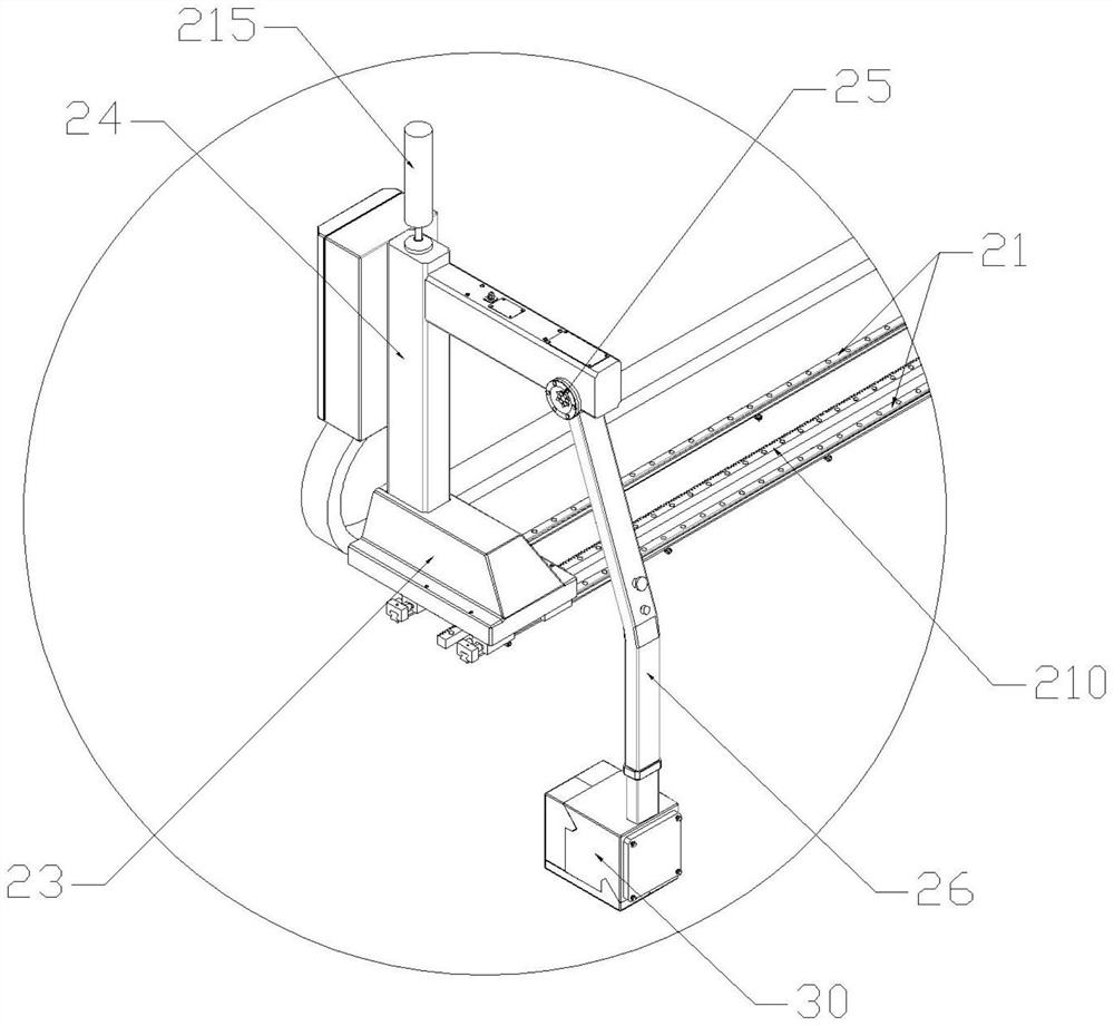
The invention discloses a threading device and automatic threading equipment. The threading device and the automatic threading equipment are installed on an embroidery machine; the embroidery machine comprises a rack, a certain number of machine heads and thread shafts arranged on the rack, and sewing threads between the machine heads and the thread shafts; a translation and swing mechanism is installed on the rack; the tail end of the translation and swing mechanism is connected with an installation and protection assembly; the installation and protection assembly comprises a shell and an installation bottom plate; the threading device is installed on the installation and protection assembly; the translation and swing mechanism is used for driving the threading device to move to the position of the machine head where threading is to be conducted and to be close to the machine head; and the threading device comprises a thread pulling mechanism, a thread leading and feeding mechanism, a calibration robot mechanism and a thread hooking mechanism on the calibration robot mechanism. The threading equipment moves to the machine head where threads are broken for threading after the threads of the embroidery machine and other textile equipment are broken, automatic threading is achieved, the efficiency of the textile equipment is improved, the labor cost is reduced, the mechanism can be directly and additionally installed on the existing embroidery machine, the interference with an existing structure is avoided, and the modification cost is low.

Description

technical field [0001] The invention relates to the technical field of textile equipment, in particular to a threader and automatic threading equipment. Background technique [0002] At present, the threading of sewing needles of textile equipment such as embroidery machines and the threading after thread breakage generally adopt the method of manual threading, which requires manual pulling and threading, which is inconvenient, laborious and time-consuming to operate. There are also some who use a threader to thread the thread, but many actions of the threader also require manual operation, and the accuracy of the threader is not enough, which affects the success rate of threading. Moreover, the threader has poor compatibility with the existing textile equipment, and is generally independent of each other, and it is easy to affect the normal operation of the equipment when integrated together. [0003] In addition, at present, industrial sewing machines, embroidery machines...

Claims


Application Information

Patent Timeline
Patent Type & Authority Applications(China)
IPC IPC(8): D05C11/00D05C11/10D05C11/22
CPCD05C11/00D05C11/10D05C11/22
Inventor 王耀奎张显磊周成钢
Owner 杭州衡论科技有限公司
Learn More