Power line storage device based on ship electrical equipment

A technology for electrical equipment and storage devices, which is applied to the field of storage devices for power cords, can solve the problems of taking a lot of time, affecting the next use, and untidy wire collection, and achieves the effects of good practicability, not easy to shake, and neat wire collection.

Pending Publication Date: 2021-08-27
BOHAI SHIPBUILDING VOCATIONAL COLLEGE
View PDF6 Cites 0 Cited by
  • Summary
  • Abstract
  • Description
  • Claims
  • Application Information

AI Technical Summary

Problems solved by technology

Usually, the current transmission method is point-to-point transmission. According to the purpose, the power cord can be divided into AC power cord and DC power cord. Usually, the AC power cord is a wire with high voltage AC. This type of wire needs a unified standard due to its high voltage. Only those who have obtained the safety certification can be formally produced, and power cords are often seen on ship equipment, but many power supply devices need to store the harness when not in use, so as to prevent the power cord from being too long to cause trampling damage to the harness and Potential safety hazards and other problems are caused, and at the same time, it is convenient to recycle for next use after storage, which requires the use of storage devices for storage operations
[0003] However, in actual use, general storage devices are easy to mix together during the storage process, which will cause the wire harness to be entangled in the next use process, and it will take a lot of time to organize, and when the storage tray is full, it will continue to be stored. As a result, the wire harness is too full during the winding process and continues to take up the wire, resulting in uneven winding, affecting the next use, which is more time-consuming and laborious, and poor in practicability

Method used


Image

  • Power line storage device based on ship electrical equipment
  • Power line storage device based on ship electrical equipment
  • Power line storage device based on ship electrical equipment

Examples


Embodiment Construction

[0027] The following will clearly and completely describe the technical solutions in the embodiments of the present invention with reference to the accompanying drawings in the embodiments of the present invention. Obviously, the described embodiments are only some, not all, embodiments of the present invention. Based on the embodiments of the present invention, all other embodiments obtained by persons of ordinary skill in the art without making creative efforts belong to the protection scope of the present invention.

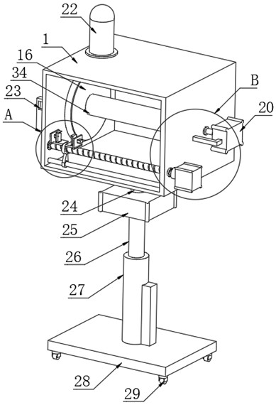
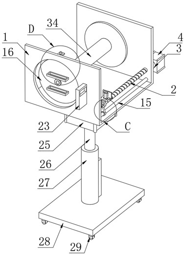
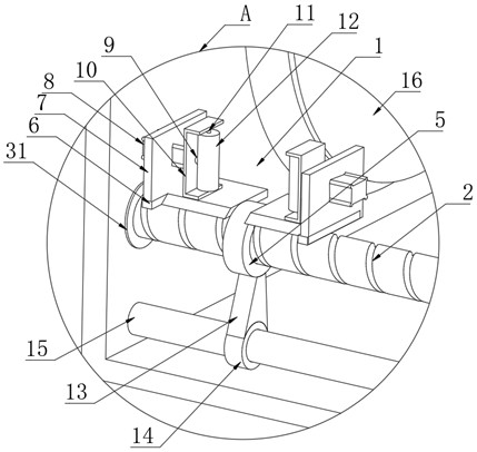
[0028] as attached Figure 1-6 The shown one is based on a power cord storage device for marine electrical equipment, including a wire take-up frame 1, and a storage mechanism is arranged inside the wire take-up frame 1, and the storage mechanism includes an alarm disassembly mechanism;

[0029] The storage mechanism includes a transmission screw rod 2, one end of the transmission screw rod 2 is connected with a rotating rod 3, and one end of the rotating rod ...


PUM


Abstract

The invention discloses a power line storage device based on ship electrical equipment, and particularly relates to the technical field of power line storage. The power line storage device comprises a take-up frame, a storage mechanism is arranged in the take-up frame, and the storage mechanism comprises an alarm dismounting mechanism; and the storage mechanism comprises a transmission lead screw, and one end of the transmission lead screw is connected with a rotating rod. According to the device, the storage mechanism and the alarm dismounting mechanism are arranged and a storage disc rotates, so that in the take-up process, power lines start to move towards one side, the power lines are orderly stored layer by layer, storage operation of the power lines with different diameters is achieved under the action of a pushing air cylinder, the device is better in applicability and more convenient to use, an alarm starts to give an alarm, at the moment, an operator can stop storage when seeing that wiring harness storage is about to be completed, the situation that the power lines cannot be taken out due to excessive storage is prevented, and practicability is better.

Description

technical field [0001] The invention relates to the technical field of power cord storage, and more specifically, the invention relates to a power cord storage device based on marine electrical equipment. Background technique [0002] Power cords are wires that carry electricity. Usually, the current transmission method is point-to-point transmission. According to the purpose, the power cord can be divided into AC power cord and DC power cord. Usually, the AC power cord is a wire with high voltage AC. This type of wire needs a unified standard due to its high voltage. Only those who have obtained the safety certification can be formally produced, and power cords are often seen on ship equipment, but many power supply devices need to store the harness when not in use, so as to prevent the power cord from being too long to cause trampling damage to the harness and Potential safety hazards and other problems are caused, and at the same time, it is convenient to recycle for nex...

Claims


Application Information

Patent Timeline
IPC IPC(8): B65H54/553B65H54/44B65H54/28B65H54/70B65H54/72B65H63/00B65H67/04
CPCB65H54/553B65H54/44B65H54/28B65H54/70B65H54/72B65H63/006B65H67/0411B65H2701/34
Inventor 蔡新梅
Owner BOHAI SHIPBUILDING VOCATIONAL COLLEGE
Why Eureka
Try Eureka