
Regional division method and device for photovoltaic power station

An area division method and technology for photovoltaic power plants, which are applied in electrical digital data processing, special data processing applications, instruments, etc., can solve the problems of no-investment construction, construction, not meeting the needs of reasonable division, and differences in the number of strings, etc. The effect of high aggregation, improved partitioning efficiency and low cost

Pending Publication Date: 2021-08-24
HEFEI SUNGROW RENEWABLE ENERGY SCI & TECH CO LTD
View PDF0 Cites 1 Cited by
  • Summary
  • Abstract
  • Description
  • Claims
  • Application Information

AI Technical Summary

Problems solved by technology

[0002] At present, before the construction of photovoltaic power stations, the division of photovoltaic arrays / confluence areas in photovoltaic power plants still relies on manual experience. The number of string point sets of each cluster is different and uncontrollable, resulting in a large difference in the number of strings connected to each combiner box. If it is applied to the actual site, the division will be messy, the specifications of the combiner boxes are different, and there is no Possibility of investment, construction, and construction, especially when encountering a complex concave plant area (that is, the outer envelope of the photovoltaic plant area is concave), the shape of the photovoltaic square array divided by the clustering algorithm is poor, and it will cross the hill or the red line area, which is easy to cause Increased cost of low-voltage cable installation hardware
[0003] Therefore, the existing methods do not meet the needs of reasonable division of photovoltaic arrays / confluence areas and other areas on the actual site

Method used


Image

  • Regional division method and device for photovoltaic power station
  • Regional division method and device for photovoltaic power station
  • Regional division method and device for photovoltaic power station

Examples


specific Embodiment

[0192] In order to facilitate the understanding of the working principle of the disclosed area division method for photovoltaic power plants, the present invention also provides a specific embodiment, as follows:

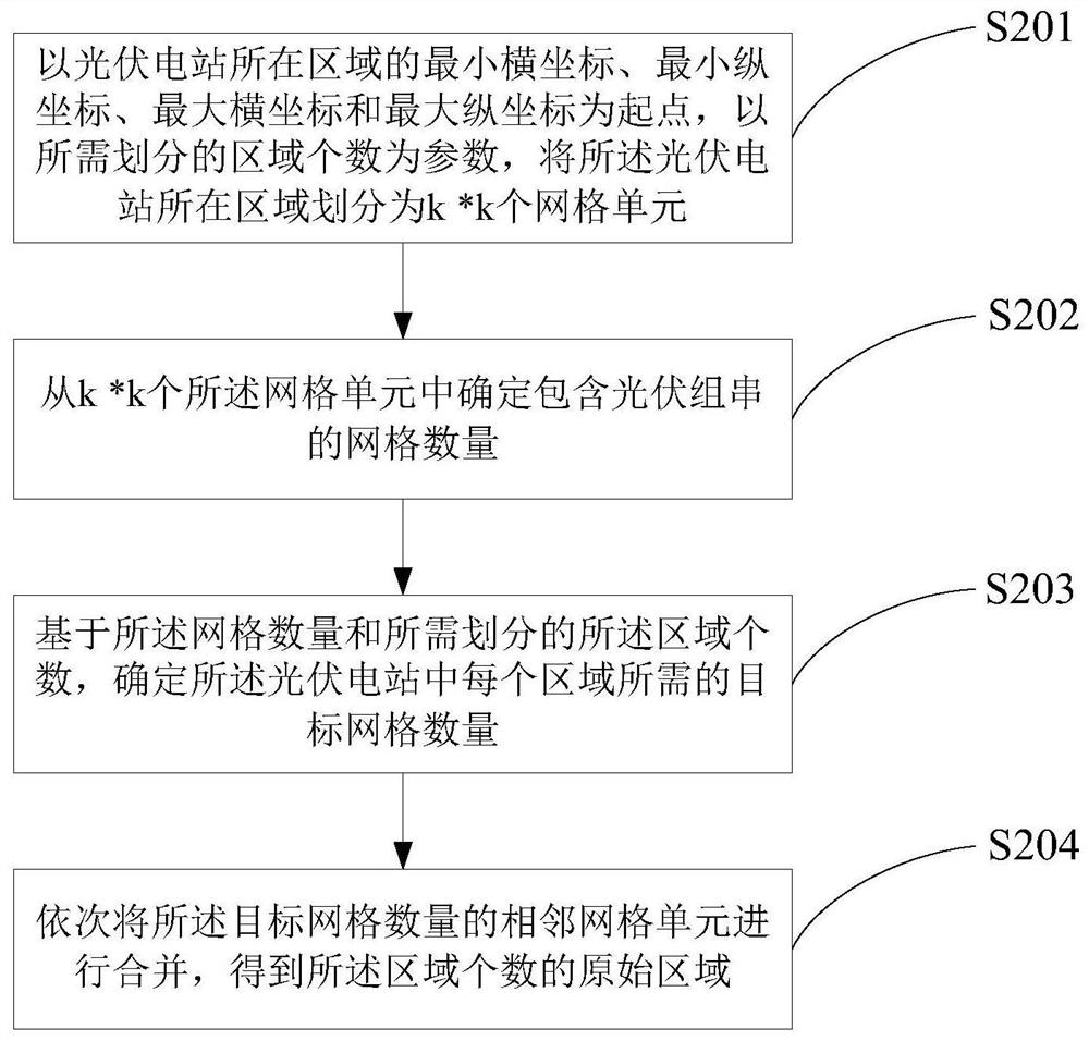
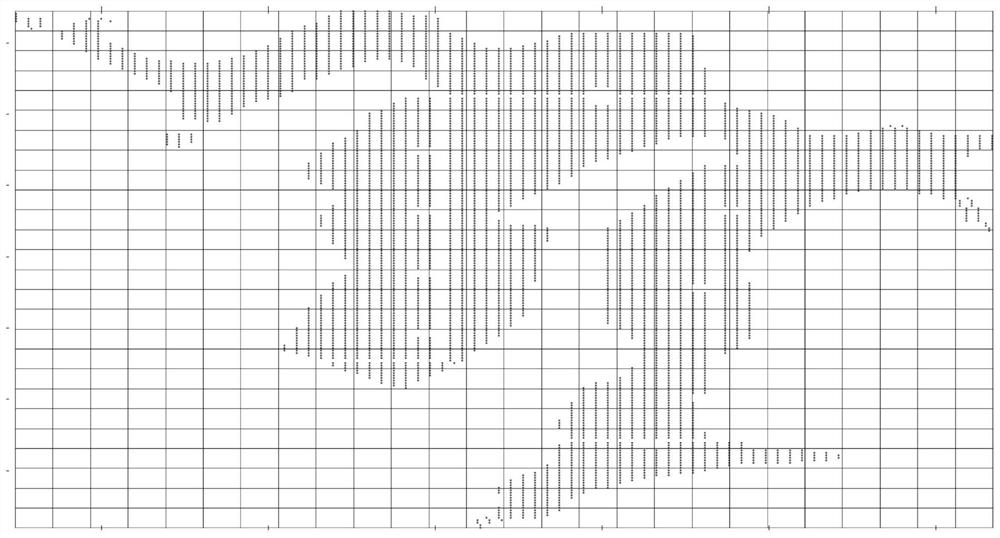
[0193] use image 3 The grid method shown in the grid divides the area of ​​the photovoltaic power station, and obtains Figure 10 Region division results for the PV plant shown; merging the sub-blocks in each region into the main block yields Figure 11 ; Match the capacity of each area to get Figure 12 , to ensure that the photovoltaic strings in the area are adjacent and have a high degree of concentration; the optimal cost / highest concentration area division scheme (including flattening) such as Figure 13 shown; as Figure 14 As shown, the capacity requirements of each area can be met through the transfer of adjacent junction points.

[0194] Corresponding to the above method embodiments, the present invention also discloses a region division device for a ...


PUM


Abstract

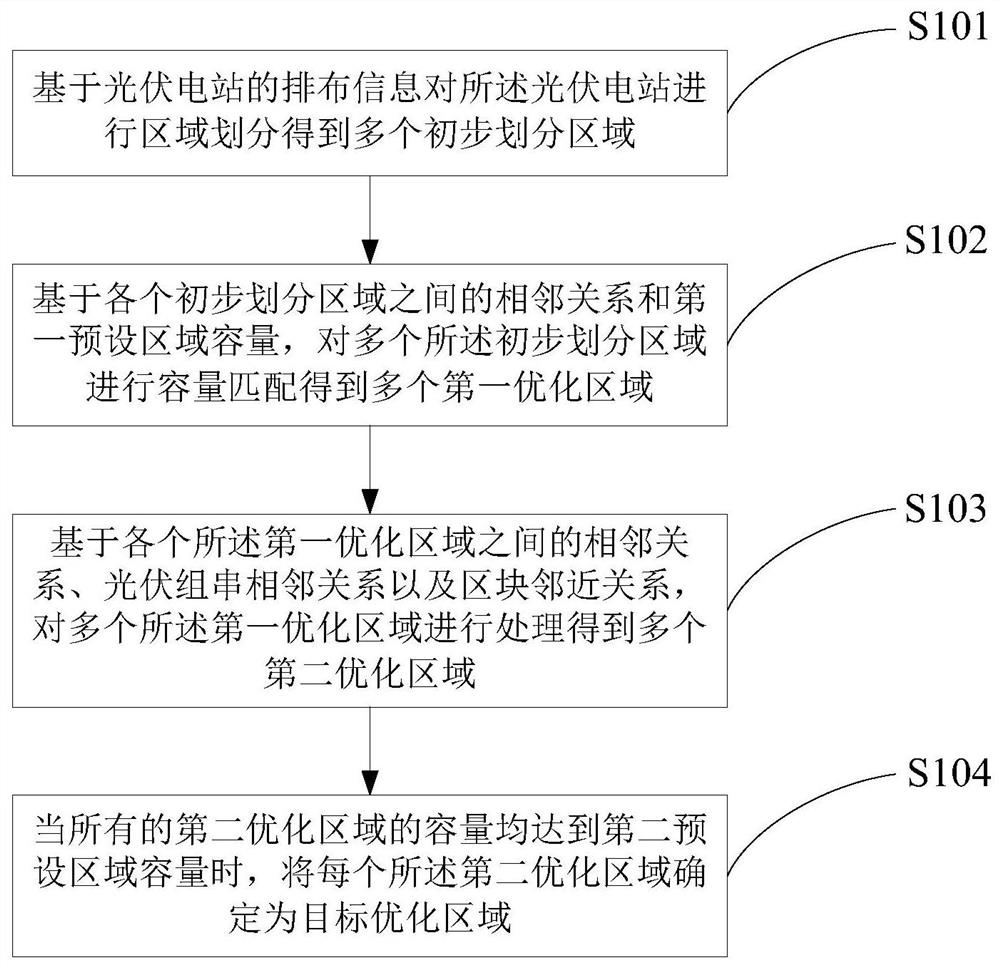
The invention discloses a region division method and device for a photovoltaic power station, and the method comprises the steps: carrying out the region division of the photovoltaic power station based on the arrangement information of the photovoltaic power station, obtaining a plurality of preliminary divided regions, and based on the adjacent relation between the preliminary divided regions and a first preset region capacity, carrying out capacity matching on the plurality of preliminary division areas to obtain a plurality of first optimization areas, and processing the plurality of first optimization areas to obtain a plurality of second optimization areas based on the adjacent relation among the first optimization areas, the adjacent relation of the photovoltaic string and the adjacent relation of the block, and when the capacities of all the second optimization areas reach the second preset area capacity, determining the second optimization areas as target optimization areas. According to the method, the regions are divided based on the arrangement information of the photovoltaic power stations, so that the photovoltaic group strings in the regions are adjacent, the capacity of each region is controllable by carrying out capacity matching on the regions, in addition, the aggregation degree of each region is the highest while the adjacent group strings in the regions are ensured, and the region division efficiency can be improved.

Description

technical field [0001] The present invention relates to the technical field of photovoltaic power plants, and more specifically, to a method and device for area division of photovoltaic power plants. Background technique [0002] At present, before the construction of photovoltaic power stations, the division of photovoltaic arrays / confluence areas in photovoltaic power plants still relies on manual experience. The number of string point sets of each cluster is different and uncontrollable, resulting in a large difference in the number of strings connected to each combiner box. If it is applied to the actual site, the division will be messy, the specifications of the combiner boxes are different, and there is no Possibility of investment, construction, and construction, especially when encountering a complex concave plant area (that is, the outer envelope of the photovoltaic plant area is concave), the shape of the photovoltaic square array divided by the clustering algorith...

Claims


Application Information

Patent Timeline
Patent Type & Authority Applications(China)
IPC IPC(8): G06F30/18G06F30/20G06F113/04G06F113/16
CPCG06F30/18G06F30/20G06F2113/16G06F2113/04
Inventor 陈朋朋刘宏博李凡
Owner HEFEI SUNGROW RENEWABLE ENERGY SCI & TECH CO LTD
Learn More