


Quick Research
Generate reliable direction feasibility study reports for your R&D in just a few steps.

Technical Q&A
Discover and master advanced knowledge NOW. Basics, ideas, possibilities, all at once.

Find Solutions
As an expert in R&D theories, this can generate solutions to your technical problems instantly.

Evaluate Feasibility
Analyze your overall solution with one click, know your potential R&D risks in advance.

Monitor Landscape
Get weekly tech updates, stay abreast of the latest tech innovations and key insights.
Internal temperature and humidity control circuit of medical equipment
A technology of temperature and humidity control and medical equipment, applied in the field of medical equipment, can solve problems such as fan startup and shutdown troubles, and low safety
- Summary
- Abstract
- Description
- Claims
- Application Information
AI Technical Summary
Problems solved by technology
Method used
Image

Examples
Embodiment 1
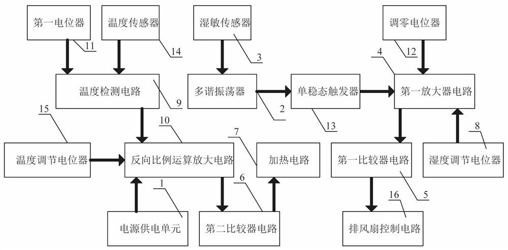
[0023] A temperature and humidity control circuit inside a medical device, such as figure 1 As shown, it includes a power supply unit 1, a second comparator circuit 6, a heating circuit 7, a temperature detection circuit 9, an inverse proportional operational amplifier circuit 10, a first potentiometer 11, a temperature sensor 14 and a temperature adjustment potentiometer 15, The first potentiometer 11 is connected with the input end of the temperature detection circuit 9, the output end of the temperature sensor 14 is connected with the input end of the temperature detection circuit 9, and the output end of the temperature detection circuit 9 is connected with the reverse proportional operational amplification The input terminal of the circuit 10 is connected, the temperature adjustment potentiometer 15 is connected with the input terminal of the inverse proportional operational amplifier circuit 10, and the output terminal of the inverse proportional operational amplifier cir...
Embodiment 2
[0026] On the basis of Example 1, such as figure 1 As shown, it also includes a multivibrator 2, a humidity sensor 3, a first amplifier circuit 4, a first comparator circuit 5, a humidity adjustment potentiometer 8, a zero adjustment potentiometer 12, a monostable trigger 13 and an exhaust fan Control circuit 16, the output end of the humidity sensitive sensor 3 is connected to the input end of the multivibrator 2, the output end of the multivibrator 2 is connected to the input end of the monostable trigger 13, and the monostable The output terminal of the state trigger 13 is connected with the input terminal of the first amplifier circuit 4, the zero adjustment potentiometer 12 is connected with the input terminal of the first amplifier circuit 4, and the humidity adjustment potentiometer 8 is connected with the input terminal of the first amplifier circuit 4 The input terminal is connected, the output terminal of the first amplifier circuit 4 is connected with the input term...
Embodiment 3
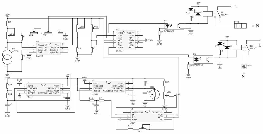
[0029] A temperature and humidity control circuit inside a medical device, such as figure 2 As shown, the temperature detection circuit 9 includes a resistor R2, a potentiometer VR3 and a temperature sensor AD590-U3, the 1 pin of the temperature sensor AD590-U3 is grounded, and the 2 pins of the temperature sensor AD590-U3 are connected in series with the potentiometer VR3 and a resistor R2, the other end of the resistor R2 is connected to +12V, and the adjustable end of the potentiometer VR3 is connected to the resistor R2.
[0030] Described inverse proportional operational amplifier circuit 10 comprises double operational amplifier LM358-U2, resistance R3, resistance R5, resistance R9 and potentiometer VR4~VR5, the 1 foot series potentiometer VR4 of described double operational amplifier LM358-U2 and resistance R5, the other end of the resistor R5 is connected to pin 2 of the temperature sensor AD590-U3, the adjustable end of the potentiometer VR4 is connected to pin 1 of ...
PUM
 Abstract
Description
Claims
Application Information
 - R&D Engineer
- R&D Manager
- IP Professional
- Industry Leading Data Capabilities
- Powerful AI technology
- Patent DNA Extraction
Browse by: Latest US Patents, China's latest patents, Technical Efficacy Thesaurus, Application Domain, Technology Topic, Popular Technical Reports.
© 2024 PatSnap. All rights reserved.Legal|Privacy policy|Modern Slavery Act Transparency Statement|Sitemap|About US| Contact US: help@patsnap.com