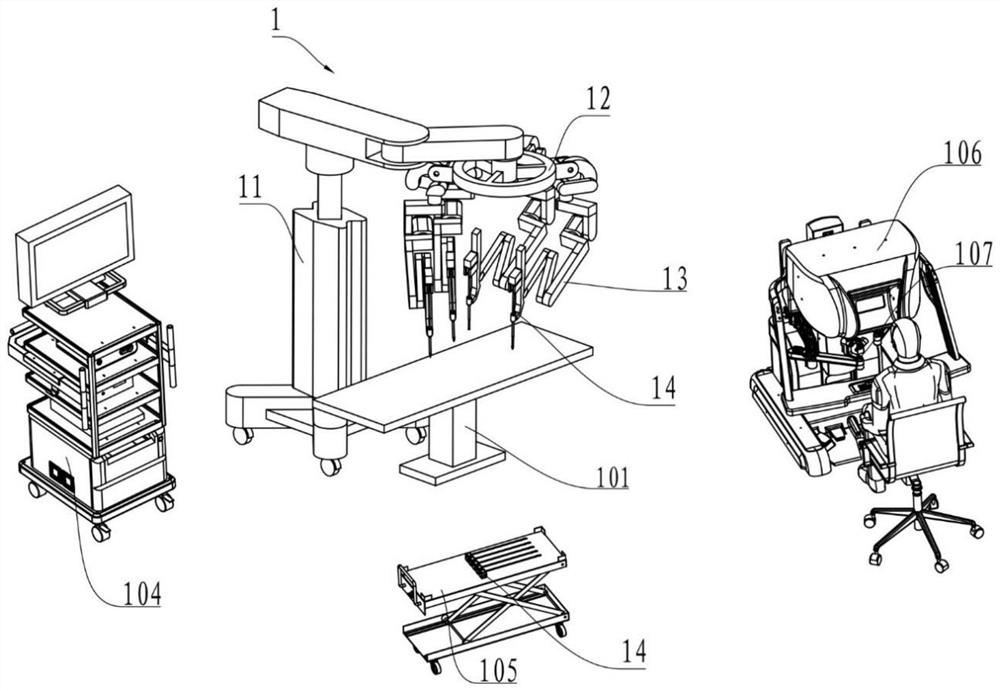
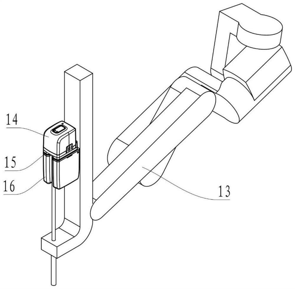
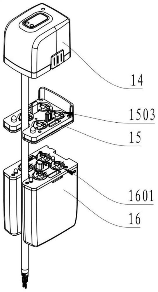
Sterile plate assembly, surgical instrument, power box and surgical robot system

A surgical instrument and board assembly technology, applied in the field of robot-assisted surgery, can solve the problems of easy shaking and tripping of sterile boards

Active Publication Date: 2021-08-24
SHANGHAI MICROPORT MEDBOT (GRP) CO LTD
View PDF7 Cites 2 Cited by
  • Summary
  • Abstract
  • Description
  • Claims
  • Application Information

AI Technical Summary

Problems solved by technology

[0006] The purpose of the present invention is to provide a sterile plate assembly, surgical instrument, power box and s

Method used


Image

  • Sterile plate assembly, surgical instrument, power box and surgical robot system
  • Sterile plate assembly, surgical instrument, power box and surgical robot system
  • Sterile plate assembly, surgical instrument, power box and surgical robot system

Examples


Embodiment 1

[0085] Please refer to Figure 4 to Figure 20 ,in, Figure 4 It is a schematic diagram of the sterile plate assembly of Embodiment 1 of the present invention;

[0086] Figure 5 It is an exploded view of the sterile plate assembly of Embodiment 1 of the present invention; Figure 6 It is a partial schematic diagram of the sterile plate assembly of Embodiment 1 of the present invention; Figure 7 yes Figure 6 An exploded view of the sterile plate assembly shown; Figure 8 is a schematic diagram of the first elastic member in Embodiment 1 of the present invention; Figure 9 It is a schematic diagram of the first locking device in the first locking position according to Embodiment 1 of the present invention; Figure 10 It is a schematic diagram of the first locking device in the first unlocking position according to Embodiment 1 of the present invention; Figure 11 is a schematic diagram of a surgical instrument according to Embodiment 1 of the present invention; Figure...

Embodiment 2

[0118] The aseptic plate assembly, surgical instrument, power box and surgical robot system of the second embodiment of the present invention are basically the same as those of the first embodiment, the same parts will not be described, and only the differences will be described below.

[0119] Please refer to Figure 21 to Figure 28 ,in, Figure 21 It is a partial schematic diagram of the surgical instrument of the second embodiment of the present invention; Figure 22 yes Figure 21 An exploded schematic of the surgical instrument shown; Figure 23 yes Figure 21 Side view of the surgical instrument shown; Figure 24 It is a transverse cross-sectional view of the surgical instrument of Embodiment 2 of the present invention; Figure 25 It is a schematic diagram of the assembled surgical instrument and the sterile plate assembly of the second embodiment of the present invention; Figure 26 It is a transverse cross-sectional view of the assembled surgical instrument and t...


PUM


Abstract

The invention provides a sterile plate assembly, a surgical instrument, a power box and a surgical robot system. The sterile plate assembly comprises a first base plate and a first locking device arranged on the first base plate; the first locking device is movably arranged between a first locking position and a first unlocking position relative to the first substrate in the first direction; the first locking device comprises a first pressing part and a first clamping part which are connected, and when the first locking device is located at the first locking position, the first clamping part is used for being locked with a component corresponding to a first target object; when the first locking device is located at the first unlocking position, the first clamping part is used for unlocking a part corresponding to the first target object; the first pressing part is configured to be limited by a second target object to move in the first direction after the sterile plate assembly is used for being assembled and connected with the second target object, so that the first locking device is limited to be located at the first locking position.

Description

technical field [0001] The invention relates to the technical field of robot-assisted surgery, in particular to a sterile plate assembly, a surgical instrument, a power box and a surgical robot system. Background technique [0002] In recent years, with the application and development of robot-related technologies, especially the development of computing technology, the role of medical surgical robots in clinical practice has attracted more and more attention. Among them, the minimally invasive surgical robot system can reduce the physical labor of doctors during the operation through interventional therapy, and at the same time achieve the purpose of precise surgery, so that patients have less trauma, less blood loss, less postoperative infection, and faster postoperative recovery. [0003] The minimally invasive surgical robot system enables the doctor to remotely control the mechanical arm and surgical tools on the slave operating robot at the main console to complete the...

Claims


Application Information

Patent Timeline
IPC IPC(8): A61B34/30A61B34/00
CPCA61B34/30A61B34/70A61B2034/305
Inventor 何裕源常新朝何超蒋友坤
Owner SHANGHAI MICROPORT MEDBOT (GRP) CO LTD
Why Eureka
Try Eureka