
Arc-shaped bottom plate drop sill underflow stilling pool

A technology of arc-shaped bottom plate and stilling pool, which is applied in water conservancy projects, marine engineering, coastline protection and other directions, can solve the problems of large amount of concrete, large elevation difference, and limited layout width of flood discharge buildings.

Pending Publication Date: 2021-08-20
POWERCHINA HUADONG ENG COPORATION LTD +1
View PDF0 Cites 0 Cited by
  • Summary
  • Abstract
  • Description
  • Claims
  • Application Information

AI Technical Summary

Problems solved by technology

[0003] However, for high dam projects in alpine and canyon areas, the layout width of flood discharge structures is often limited, the single width of flood discharge is large, the flow is large, and the energy is concentrated, and the design of energy dissipation for bottom flow stilling basins is still very difficult.
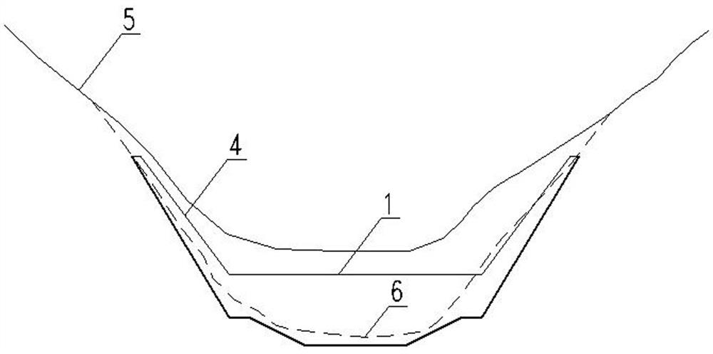
In addition, for high dam projects in alpine and canyon areas, due to the relatively deep rock cutting and thick covering layer in the channel, the elevation difference between the center of the channel and the bedrock floor on both sides is often large, and the thickness of the bottom plate in the middle of the stilling pool is often much greater than the thickness of the bottom plates on both sides. , leading to a large amount of concrete in the bottom flow stilling basin, and the economy is relatively poor

Method used


Image

  • Arc-shaped bottom plate drop sill underflow stilling pool
  • Arc-shaped bottom plate drop sill underflow stilling pool
  • Arc-shaped bottom plate drop sill underflow stilling pool

Examples


Embodiment 1

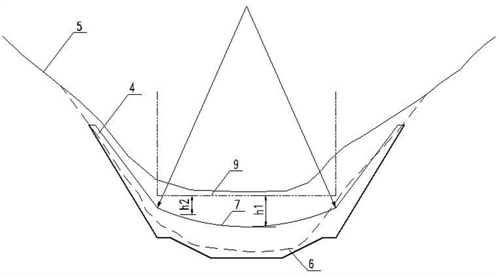
[0024] The bottom plate of the stilling pool in Embodiment 1 is an arc-shaped bottom plate stilling pool 7, and the cross-section of the top surface of the bottom plate perpendicular to the direction of water flow adopts an arc curve, thereby forming an arc-shaped bottom plate falling sill stilling pool. In this example, a 1:60 scale flat-bottom stilling pool of a project is used (such as Image 6 , Figure 7 ) and curved bottom sill stilling basin (such as Figure 8 , Figure 9 ) hydraulic model test has verified the effectiveness of the present embodiment.

[0025] A project is a second-class (2) type project, using a concrete gravity dam, the maximum dam height is 123m, and the flood discharge of the checked flood (P=0.05%) entering the reservoir is 10600m 3 / s, design flood (P=0.2%) inflow flood discharge 9410m 3 / s, energy dissipation design (P=2%) flood flow into storage is 7380m 3 / s. The valley at the dam site is narrow and basically symmetrical "V" shaped canyon...

Embodiment 2

[0034] Compared with Embodiment 1, the cross-section of the top surface of the stilling basin floor perpendicular to the water flow direction of the arc-shaped bottom plate falling sill stilling basin of this example adopts an elliptic curve.

Embodiment 3

[0036] Compared with Example 1, as Figure 10 As shown, the top surface of the bottom plate of the stilling pool with arc-shaped floor and falling sill in this example adopts a curve composed of a circular arc and a straight line. Use flat.


PUM


Abstract

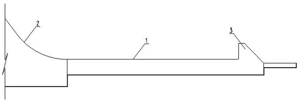
The invention relates to an arc-shaped bottom plate drop sill underflow stilling pool. The arc-shaped bottom plate drop sill underflow stilling pool is suitable for a bottom flow energy dissipation technology of high water head, large flow and narrow river valley. The arc-shaped bottom plate drop sill underflow stilling pool is simple and feasible in structure, can effectively improve the energy dissipation rate and reduce the construction cost, and has a good application prospect. According to the technical scheme, the arc-shaped bottom plate drop sill underflow stilling pool is arranged at a discharge chute outlet of a flood discharge building and is characterized in that a drop sill is formed between the top face of a bottom plate at the head of the stilling pool and the discharge chute outlet; the height of the drop sill gradually changes in the transverse direction; and the height h1 of the middle of the drop sill is larger than the height h2 of the two sides of the drop sill.

Description

technical field [0001] The invention relates to a bottom flow stilling pool with a curved bottom plate, which is suitable for the bottom flow energy dissipation technology of high water head, large flow and narrow river valleys. Background technique [0002] Bottom flow energy dissipation is a commonly used energy dissipation method in water conservancy and hydropower projects. Underflow energy dissipation has the advantages of reliable operation, stable flow state, strong adaptability to geological conditions, and slight atomization of flood discharge. Early bottom flow energy dissipation was mostly used in middle and bottom water head projects. For high water head projects, due to the high hydraulic indicators such as flow velocity and pulsating pressure in the stilling basin, the risk of damage to the stilling basin is relatively high, and the use of bottom flow energy dissipation is less. In recent years, with the construction of projects such as Xiangjiaba and Guandi, ...

Claims


Application Information

Patent Timeline
IPC IPC(8): E02B8/06
CPCE02B8/06
Inventor 吴伟伟徐建军李伟史彬李英勇刘西军薛阳
Owner POWERCHINA HUADONG ENG COPORATION LTD
Learn More