Packaging machine clamping and sealing heating device

A heating device, packaging machine technology, applied in packaging sealing/tightening, packaging, transportation packaging and other directions, can solve the problems of difficult to guarantee movement accuracy and complex structure

Pending Publication Date: 2021-08-20
多科智能装备(常熟)有限公司
View PDF1 Cites 0 Cited by
  • Summary
  • Abstract
  • Description
  • Claims
  • Application Information

AI Technical Summary

Problems solved by technology

The structure of the utility model is complicated, and the action accuracy is difficult to guarantee

Method used


Image

  • Packaging machine clamping and sealing heating device
  • Packaging machine clamping and sealing heating device

Examples


Embodiment 1

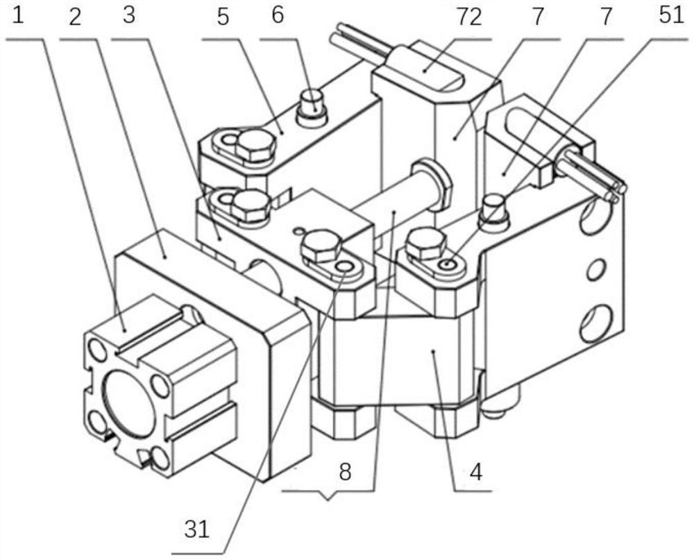
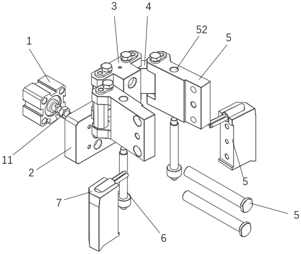
[0027] The invention provides a packaging machine clamp sealing heating device, such as Figure 1-2 As shown, it is mainly used in the heating link in the longitudinal sealing process of the vertical packaging machine, including the power cylinder 1, the fixed seat 2, the sliding seat 3, the hinge block 4, the rotating block 5, the fixed shaft 6 and the heating block 7. The power cylinder 1 can be a pneumatic power cylinder or a hydraulic power cylinder, which is provided with a transmission shaft 11, and the transmission shaft 11 can be stretched. The fixed base 2 is fixed on the frame or base of the packaging machine (not shown in the figure), and does not move relative to each other as a fixed part, and is preferably a square or circular disc-shaped structural block. The power cylinder 1 is connected to the side of the fixed seat 2, and its power transmission shaft 11 is connected with the sliding seat 3 after passing through the shaft hole provided on the fixed seat 2. Sl...

Embodiment 2

[0033] This embodiment 2 is formed on the basis of embodiment 1. Through the guide rod and the elastic member sleeved on the guide rod, the operation stability of the clamping heating device of the packaging machine is improved, and at the same time, excessive Heat radiation causes the laminated film to stick to the heating block. specifically:

[0034] Such as Figure 1-2As shown, a guide rod 8 is also provided in the clamping and heating device of the main packaging machine. Corresponding shaft holes are provided on the sliding seat 3, and one end of the guide rod 8 is fastened to the fixed seat 2. The connection method The other end of the guide rod 8 can pass through the shaft hole on the slider 3 and extend to a certain distance outside the slider 3 by means of screw connection or welding, and the guide rod 8 and the slider 3 are slidably connected, that is, the guide rod 8 can slide freely in the shaft hole of slide seat 3. After the guide rod 8 is connected with the ...


PUM


Abstract

The invention relates to a packing machine clamping and sealing heating device in the technical field of packing equipment. The packing machine clamping and sealing heating device comprises a power cylinder, a fixed base, a sliding base, a hinge block, rotating blocks, a fixed shaft and a heating block. Two first hinge shafts are symmetrically arranged on the two sides of the sliding base, second hinge shafts are arranged at one ends of the rotating blocks, second shaft holes are formed in the middles of the rotating blocks, and the axes of the second shaft holes are parallel to the axes of the second hinge shafts. The power cylinder is connected to one side face of the fixed base, a transmission shaft of the power cylinder penetrates through the fixed base and then is connected with the sliding base, the first hinge shaft is rotationally connected with the second hinge shaft through the hinge block, and the fixing shaft is rotationally connected with the rotating blocks through the second shaft holes. The two sets of rotating blocks are arranged on the two sides of the sliding base respectively, the two heating blocks are connected to the other ends of the two sets of rotating blocks respectively, and the heating faces of the two heating blocks are oppositely arranged. By applying the connecting rod type structural design, the structure is simple, the action is accurate, the distance between the two heating surfaces is effectively controlled, and the heating and plastic sealing effect on a folded film is improved.

Description

technical field [0001] The present invention relates to the technical field of packaging equipment, in particular to a sealing heating device for a packaging machine. Background technique [0002] The film sealing is usually done by a horizontal sealing machine. The horizontal sealing machine usually includes two clamping components and a driving mechanism. Driven by the driving mechanism, the clamping components are brought close to each other. After the two clamping components clamp the film material , using the heat-sealing roller on the clamping assembly to bond the film materials together. A traditional horizontal sealing machine usually uses a drive unit to drive one of the clamping components to reciprocate, so as to approach or move away from the other clamping component. The horizontal sealing machine with this structure is responsible for the decoupling unit, and the movement stroke of the single clamping component in the reciprocating motion is relatively large, ...

Claims


Application Information

Patent Timeline
Patent Type & Authority Applications(China)
IPC IPC(8): B65B51/26
CPCB65B51/26
Inventor 王振洪坚
Owner 多科智能装备(常熟)有限公司
Why Eureka
Try Eureka